Wireless DVB-C
Introduction:
Operators well understand importance of continuous subscriber base expansion which first of all can be reached due to cover zone expansion. Thus it is extremely desirable to have the centralized network with the only one Central Station (CS). Practically in all large cities there are rather densely populated suburbs, satellite towns and suburban settlements on which cable operators seek to expand a coverage area of the subscriber network. However often to deliver there the signal to the operator happens not so simply because of the high works cost on an optical fiber laying, difficulties to projects coordination and some other the reasons. In this article it will be discussed a question of these difficulties overcoming possible ways due to wireless decisions application. Our offers are based not only on the theoretical analysis, but also on examples of the real projects realized with our help by acting operators. In this article we will share experience of such systems creation.

Cable – Optics – RRL – the Broadcasting:
In the beginning some words about possible algorithm of the TV broadcasting cable networks development, about their history and prospects. There will be no statement wrong that actually each cable operator began the business just with a coaxial network development, on that he "cable" operator is. With fiber-optic communication lines development operators started using them for laying of the main lines, and over time – and for a signal distribution to the house. Advantages of fiber-optic in relation to a coaxial cable can't be underestimated but fiber application as it was noted above isn't always economically justified. In that case wireless means, and first of all LOS radio relay lines (RRL) can replace fiber. On modern RRL it is possible to transmit signals with difficult types of digital modulation which are similar to the DTV signals transmitted on cable networks (for example, QAM64). It allows to simplify and reduce the price significantly of a cable network signaling on long distances because in radio relay stations (RRS) on the transferring block input the group signal with Central Station (CS) simply is given, and on the reception part this group signal is used for the subsequent distribution. Earlier in case the regional cable operator wanted to expand a cover zone of the network on the neighboring settlement, in most cases it had to build new CS in this settlement. Due to RRS use there was an opportunity rather cheap to expand, scale and configure a cover zone. Especially as the method of a signal delivery to the subscriber remained habitual for all operators – on a cable network. Only a source of a signal is not CS, and the RRS receiver. Those from operators who to connection of the networks already applied RRS, understood what even need of obtaining permission to use of frequencies for RRL doesn't outweigh all benefits from use of such technology for a network expansion. They were convinced that this procedure not such and difficult as can seem at first sight. Point-to-point RRL solves a problem of connection between cable networks. However in certain cases the problem consists not only in signal delivery to the hubs, but also in creation of the distribution network. Sometimes expenses of time and funds for a cable lying on not really densely populated suburb aren't justified, and at the same time "fixing" in this area is desirable and perspective and besides–urgent. How without excessive expenses to meet all these requirements? In such situation usually applied well all the familiar TV broadcasting technology – MMDS which works in the range of frequencies occupied also by mobile communication systems that causes difficulties at its introduction. By means of the broadcasting systems which equipment works in other available frequencies ranges, it is possible to cover with a signal all necessary territory. For this purpose it is possible to use the wireless repeater working in any available frequencies ranges from 2 to 30 GHz, i.e. actually to organize of your cable network signal delivery to the house of each subscriber without lying of cables in general. Installation of such system together with installation of intakes takes some days from subscribers. Thus subscribers of a wireless network, as well as subscribers of a cable network, use standard reception tuners as by wireless transfer all signal parameters – modulation mode, a signal scrambling system of conditional access, service table’s creation, etc remain. The final subscriber won't feel a difference in connection. It should be noted only some complication of the subscriber equipment – for wireless reception rather inexpensive reception converter, the satellite antenna with necessary gain factor and a power supply injector will be necessary for the reception converter, i.e. actually a set for reception of satellite TV. Approximately so evolution of the cable operator network at expansion of its cover zone looks. The positive moment is that the described decisions are already realized and are operated, and the operator who has made the decision to introduce at similar system, won't be a pioneer. Therefore in the following section we will tell about the principles of real systems creation.
Networks expansion primers:
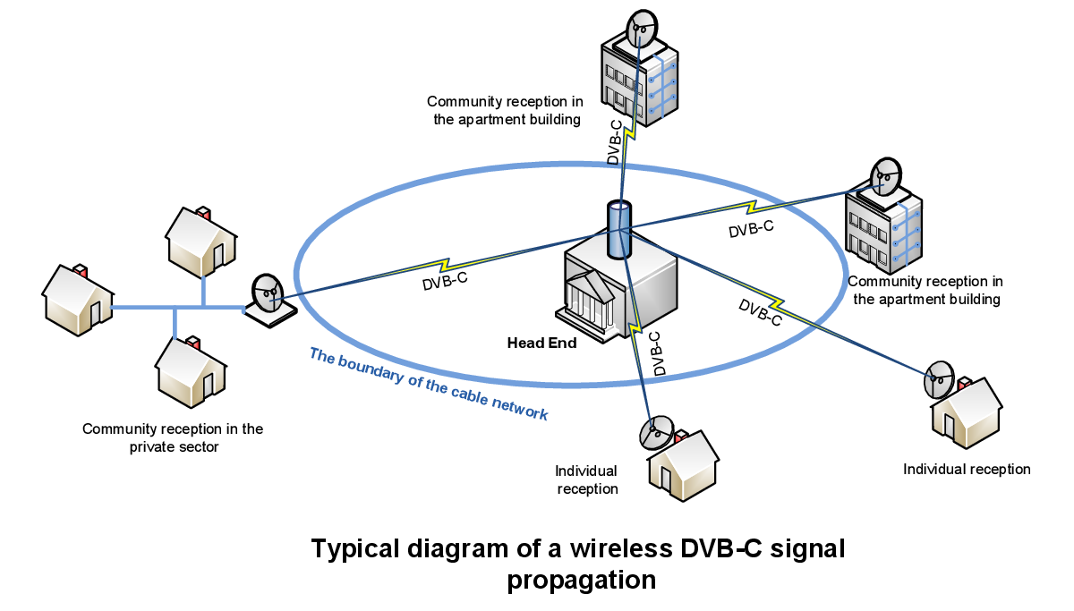
1. Covering of suburbs. To us the CATV operator made an inquiry on production of the equipments set working in the frequencies range allowed for it which would intend for signal translation from its cable network on the nearby suburb since to develop there a cable network was economically inexpedient. The decision to cover with the signal consisting of 12 carriers, both the city and the suburb at the same time since and in city boundaries were at home yet not connected to its network was made. The broadcasting had to be carried out from a roof of Central Station building evenly in all directions (on 360°), covering all necessary territory. Shadow zones (sites in the general cover zone where the signal doesn't get because of LOS mode lack) had to be served by micro repeaters (inexpensive low-power repeaters). Opportunity, as collective reception (one receive converter and the antenna on an apartment house or a little private), and individual reception for the private sector (one reception converter and the antenna for each user) was assumed. Thus in case of collective reception it is possible to apply more highly stable reception converters, i.e. more expensive, and for individual reception it is possible to propose the inexpensive available solution. This system was constructed and successfully brought into commercial operation. The signal covered the territory more than 10 km in the diameter, relaying of broadcasting signals in the shaded sites, collective and individual reception were realized. At hybrid network subscribers the same standard cable tuners and cards of conditional access system as well as at other cable network subscribers were installed. Thus, the hybrid cable network which has allowed the operator quickly to expand a cover zone of a network was created and to increase number of subscribers. Thus development of actually cable network was continued as on time expiration can prevent to switch nothing at the subscriber a wireless source of a signal on wire.
2. Covering of the neighboring settlements. This is example of other operator. Development of an existing cable network came to a standstill; almost all potential subscriber bases in this settlement were captured. And, as we know, it is impossible to stop in development in any way. Therefore the decision to expand network action on the neighboring settlements was made. In this situation, unlike the previous case, it was decided to go some other way. Since a large number of repeating and a signal transmission on a long distance was expected (because of a hilly cross-country terrain), it was necessary to apply more noise proof modulation with the best power parameters, than QAM64. QPSK modulation was applied, i.e. was actually decided to build a broadcasting network by the principle of MITRIS system (the simple table showing efficiency of use of frequencies bands depending on applied modulation) is given below. It allowed to develop quickly enough relay flights with broadcasting repeaters for a full covering a signal of the neighboring settlements. Thus subscribers could use a usual set of the reception equipment of satellite TV without any completions.
3. Application of a broadcasting/distributive network. We will give one more option of a hybrid network. Here the wireless network at the same time plays a role, both a distributive network, and a broadcasting network. The CATV operator constructed earlier independent cable networks in several neighboring settlements, but service of these separate networks for one operator was difficult. Association of networks in one with use of one general CS was required. The transformed network looked as follows: all settlements as well as earlier were served by the cable networks the signal in which arrived through a network of relay and broadcasting lines which at the same time covered the territory and broadcast a signal with QPSK modulation to a reception place. Here the signal with QPSK modulation was transmodulated in a signal with QAM64 modulation also moved in the CATV network. Thus, the operator obtained stable communication lines (flights between the transferring and reception equipment in wireless systems) between the networks with a simultaneous covering a territory signal for fast connection of subscribers to whom the cable network isn't brought, kept all subscriber equipment and had to control only one central station.
In the examples given by us it is shown how it is possible to expand a cover zone due to interaction of wireless and wire decisions and to complicate a configuration of a uniform hybrid broadcasting network, increasing such way number of served subscribers and facilitating network service by the operator.
The table of a frequency resource use efficiency for two modulation types at a broadcasting of 200 MPEG-2 SD channels
| Parameter/Modulation | QPSK | QAM64 |
|---|---|---|
| Frequencies range of transferring signals, GHz | ||
| Standard frequency band of subscriber’s devices, MHz | 1000 | 200 |
| Standard one carrier’s band, MHz | 36 | 8 |
| Average bitrate on one carrier, Mbps | 38 | 32 |
| The average fixed bitrate of one channel, Mbps | 3.5 | 3.5 |
| Average number of channels on 1 carrier | 10 | 8 |
| Carrier quantity for 200 channels placement | 20 | 25 |
| Maximum radius of a covering zone, Km | 30 | 10 |
| Demanded frequencies strip on air, MHz | 720 | 200 |
| Structure of a subscriber set | Satellite receive antenna, satellite LNB, satellite set top box | atellite receive antenna, standard satellite LNB or modified (depending on a system configuration), LNB power supply injector with power supply block, cable set top box |
Authors

P. Y. Ksionzenko
CEO of ROKS

Ievgenii Kukhol
Leading engineer of ROKS

