Base Station Architecture Supporting On-Air Frequency Multiplexing (Variants)

Ukrainian Patent № 54644, 25.11.2010
P. Ksenzenko, M. Boichenko, P. Himich,
“ROKS”-company
The invention concerns a multichannel digital television and audio broadcastings systems, including – to networks of a multichannel single frequency synchronous broadcasting (multichannel SFN).
The device which includes the frequency downconverter which serves for conversion downwards on frequency, at least, the first and second radio-frequency signals for obtaining, at least, the first and second lower frequency signals and the multiplexer which serves for multiplexing, at least, the first and second lower frequency signals for the purpose of a multiplexed on frequency signal reception [1] is known.
The invention is based on the statement that noise sources can bring the correlated noise which is added to the received parallel branches signals (for example if the invention is realised in the equipment on the basis of silicon in parallel receive branches, and in receive branches for signal processing the general frequencies synthesizers or when at the silicon equipment somewhere there are general sources of noise) are used. The correlated noise can lower data transmission rate or information capacity of the data link in the receiver. The invention is based on the statement that at frequency multiplexing, at least, the first and second radio-frequency signals in the general multiplexed signal noise sources cannot bring the correlated noise in the received signals as at their consecutive multiplexing of the low frequency first and second signals frequencies band are divided further. Thus, each of separate signals united in a multiplexed signal is affected various not correlated spectrum components of noise sources. As a result of it the noise level in the received signal decreases.
The lack of the specified device consists that the receiver and transmitter architecture is intended for systems with many transmit and many receive antennas (MIMO) and has for an object decrease in noise level in the receiver at the frequency multiplexing expense of the several received signals on intermediate frequency. Multiplexing in this device is made on an intermediate frequency that is at physical level, instead of in the propagation environment. In the given system frequency multiplexing realises auxiliary function in system MIMO – at the expense of a noise level reduction at receiving it allows to system throughput increase and its information capacity increase. MIMO on itself assumes spatial multiplexing and is effective only in the propagation conditions to which presence a great number of the strong reflected signals (the Rayleigh mode) is peculiar, and is ineffective at the modes close to “line–of-sight” mode.
Multiplexing on IF lack is necessity for power amplifiers to gain multiplexed (that is multifrequency) signals that demands from them the raised linearity. The requirement of the raised linearity causes low amplifiers efficiency. In MIMO transmitters gain only the signals and radiate them through the antennas, but each of them will gain a multifrequency signal, and therefore requirements to linearity of its amplitude characteristic increase.
In transmit channels the signals received by means of a method orthogonal frequency multiplexing – OFDM, or its version – COFDM which are formed by means of return fast Fourier transformation – IFFT can be used. These signals are created in the transmit channel and consequently the method OFDM (COFDM) is considered as modulation method, instead of by channels multiplexing methods and at merits and demerits studying of various multiplexing schemes it cannot to be taken into consideration.
The device which assumes application of not electric (mainly fiber-optic) internal connections between the baseband processor and the radio-frequency transceiver mounted on a towering platform (tower), that is with use of the known standard equipment placing principle for communication systems. Replacement an electric line of a baseband signal transmission in the coaxial cable or twisted pair form which connects processor with the radio-frequency (RF) transceiver on a fiber-optic cable promotes baseband equipment protection (the channel forming equipment) from currents which induced at lighting discharge and which translate downwards on an electric cable (in particular – on a coaxial cable). Supply voltage and communication signals transfer is usually made from the channel forming equipment to placed on tower top RF transceiver by means of one or several cables (including coaxial cables).
On these cables transfer of lighting discharges induced currents (which arise at lightning hit in the antenna) is possible, for a set of that can to be damaged both a cable, and the baseband processor together with the interface and other equipment placed with the tower basis or near to it.
According to the specified device potential risk of influences on the baseband equipment induced by lighting discharges currents which are flowing down on a coaxial cable, it is excluded by replacement of electric connections (coaxial cables) on not electric (fiber-optic cables). As a result of such replacement at lightning hit in the antenna the induced currents not translate to the baseband equipment which settles down about the tower basis. The best at such replacement are the fiber-optic cables, which interfaces with the baseband equipment and RF transceiver realized in the form of electrooptical and optoelectrical converters. Except communication signals, on fiber-optic cables the duplex management signal can be transmitted.
A supply voltage for RF transceiver moves on a tower by means of a separate electric line which should be reliably protected inclusion of corresponding protectors and due shielding [2].
The specified device lack is that in it fiber-optic cables are used for baseband signalling. It causes the modem equipment placing at tower top, increasing thereby the working in more severe conditions equipment quantity. If in system the frequency multiplexing on air method is used that is each transmit channel is transmitted by means of separate transmitter and antenna such construction will be unprofitable as at it the quantity of the equipment located at a tower top and subject influence lighting discharges and industrial disturbances considerably increases.
To the reasons, disturbing to achievement of expected technical result at use of the known device, that in it on a fiber-optic cable the baseband signal is transmitted that leads to necessity of placing at a tower top the modem equipment which is compelled to work in more severe conditions concerns, and by transmitting of channels set in multichannel system on single fiber-optic cable system stability to disturbances decreases and requirements to converter linearity increase.
Closest of devices which is used on the same appointment, as declared, the device which has usual system of transmitting antennas for base station with input terminals set, set of multiplexers – transmitters which consist bandpass filters set, the connections blocks connecting their inputs, output terminals which are connected to one of antenna system input terminals, and also transmitters set which are grouped according to filters frequencies connected to their inputs is. Transmitters multiplexers bandwidth choose so that all their bandwidths were located in the full frequencies range intended for given mobile communication system. Feature of transmitters groups is their ability automatically to retune frequencies of a multichannel radio signal according to a band. Thus, the system can operatively be switched from the channel to the channel.
In the specified device the frequency multiplexing method for transmitters in a land mobile communication system at which use probably essential reduction of transmit power level change even when frequency on which the transmitter works, quickly changes the value in the allocated frequency range is introduced. Application of such system allows minimize the general losses and nonlinear distortions even in cases of the general antenna system use for set of multichannel transmitters.
In the specified device the multiplexing system is applied to transmitters of the mobile communications land systems, using antenna systems in which antennas elements are located so that to prevent a mutual interference or to get an antenna surface with elementary vibrators set, each of which has an independent input and has such execution which allows to exclude a mutual interference; multiplexers set of the transmitters connected by means of feeders system to the general antennas system and combining signals, arriving from bandpass filters (BPF) set; the connections block connecting BPF inputs set, which output terminal is connected to one of antennas system input terminals [3]. The specified device is chosen as a prototype.
Specified devices lack is that the multiplexer in the given device, in essence, is the complicated variant of the multiplexer which is usually used for multiplexing at physical level, namely, - at level RF parts of a transmit path on a joint with antennas system. Such multiplexer consists bandpass filters set and the same quantity ferrite circulators. If the system is multichannel signal losses in the multiplexer of this kind will be big enough. The multichannel signal is radiated in an air by antennas system which consists of the elementary vibrators connected to the help of hybrid bridges. Receive and transmit signals are divided with the help of duplexer which consists from three-branch ferrite circulator and two filters. In the given system during each moment of time by means of the switchboard everyone filter output of any transmitters groups is connected to an antennas system. The duplexer, the switchboard and filters together make the multiplexer.
Multiplexing in the specified device make not in the propagation environment, and on physical (PHY) level as the multiplexer is located before an antennas system especially lacks of the resulted scheme will be obvious to base stations with the big radiated power also. Between transmitters output and an antennas system input the difficult multiplexer which incorporates set of filters, the switchboard and circulator is included, each of which brings the contribution to signal losses. Inevitable big signal losses in the multiplexer for which account the signal arrives in antenna system weakened, are the main lack of a prototype.
The task in view dares because a television and audio broadcasting network in a frequency multiplexing mode in the propagation environment are included by the multiplexer connected to transmitters outputs and antenna system input, and also N – omnidirectional antennas which are connected with N – transmitters in the powerful upconverters form connected with N – channel crossover which is connected with N – bandpass filters which in the first variant are connected to single-channel optical receivers which through a multicore fiber-optic line are connected to inputs N – optical transmitters, and the power supply is connected with N – channel crossover and N - single-channel optical receivers, and in other variant N – bandpass filters are connected to block N – transmodulators with synchronization schemes with a support on signals GPS which are connected with the low noise downconverter block (LNB) which is connected to antenna a receive RRS.
In the declared device for the losses reduction purpose and an exception of increased requirements to transmitters linearity, and also for increase the general stability of system to disturbances and reduction of its total cost in system frequency multiplexing in the propagation environment (on air) and separate channels transmitting on IF from CS to BS set on multicore fiber-optic cables or on radio relay communication lines is used.
Starting with declared, connection specified known signs and essential signs set of the declared device provides essential increase in the service zone sizes. It is reached at the expense of increase for each separate radio channel of radiated power, and also at the expense of a multichannel single frequency synchronous broadcast network construction possibility obtainment in which in the centers of mutually overlapping cells the declared devices (Base stations) take places. Accompanying useful system signs are increase the single-channel transmitter efficiency and simplification and reduction in base stations price possibility because at IF signaling on separate veins of multicore fiber-optic cables the system synchronization becomes simpler, signal losses decrease and system firmness to disturbances raises. Besides, lighting protection becomes more reliable.
The essence of the offered useful model is explained by the figures represented on: Fig.1 – the system block diagram (the Variant 1), Fig.2 – the system block diagram (the Variant 2).
The design of an equipment radio-frequency part (the Variant 1 and the Variant 2) and its elements for both variants remains without changes. In the equipment are applied: N – omnidirectional antennas (ANT1 – ANTn), N – transmitters in the powerful upconverters form (BUC1 – BUCn) 2, crossover N – channel 3 and N – bandpass filters (BPF1 – BPFn) 4. On it similarity between two variants comes to an end.
Other part of a complex works thus: (Variant 1) Separate channels signals on IF which have modulation QAM64 (DVB-C) or COFDM (DVB-T), arrive on inputs of N optical transmitters 7. Here they will be converted to an optical range and transmitted on separate veins of a fiber-optic cable 6 which connects a studio part of a complex to that its part which it is placed at tower top (in an installation site of a radio-frequency part). This part begins with single-channel optical receivers 5 which will convert optical signals back to IF signals. At the expense of signaling on a fiber-optic line all problems allied with a signal losses will be remove, and also high immunity from disturbances is reached. The distance on which the signal on fiber-optic line can be transmitted, can reach 15 Km and more.
The main differences of declared system from existing will be the following:
- Use of single-channel transmitters signals frequency multiplexing method in the propagation environment (on-air) by means of omnidirectional antennas system, - IF signaling of separate channels from a studio complex part to its part which settles down at tower top, by means of the multicore fiber-optic cable including in the design a conductor which serves for supply voltage giving from the power supply 8 on a radio-frequency part of a complex and optical receivers. Such construction allows to transmitting signals on the big distances and excludes noise and disturbances accumulation on fiber-optic line. Signaling possibility on the big distances and maintenance thus high noise immunity in the conditions of the industrial disturbances action, reached at the expense of fiber-optic cables use, allows construct on the basis of given BS a network of a single frequency synchronous broadcasting (SNF) for each of channels set, which are multiplexed in the propagation environment.
Thus signals from network CS (the Studio complex) to a part of network BS on fiber-optic cables that allows organize a single frequency synchronous broadcast network for each of channels. Besides, as delays by transfer on fiber-optic line on distances of several tens kilometers are very small and can be in advance defined, and the reflected signals are absent, synchronization of all network is reached on CS by a delay dispersion correction in each of channels. At the big sizes of a network it can give considerable economic benefit as the corrector quantity will be minimal.
BS block diagram, which is represented on Fig.2 (the Variant 2), assumes use in networks in which for any reasons lining fiber-optic cables for connection CS with BS set is impossible. In such networks instead of fiber-optic it is offered to use simplex radio relay communication lines (RRL). By group multichannel signals transfer on RRL frequency multiplexing, but reached on PHY level also is used. Signaling on RRL and a broadcasting by means of BS are made with different standards signals use (DVB-S – on RRL and DVB-T – for a broadcasting on BS), therefore for the purpose of signals conversion from one standard in another in paths of signal processing it is necessary to establish the transmodulators QPSK/COFDM block 5 (Fig.2) in which transport streams processing is provided.
For group multichannel signals transfer on RRL frequency multiplexing, but reached on PHY level also is used. Therefore synchronization in SFN should be carried out already on BS, and on CS pilot-signals are entered.
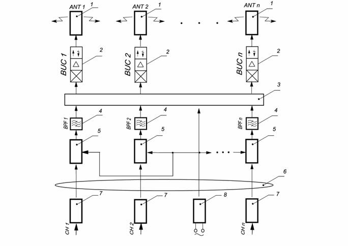
Fig.1
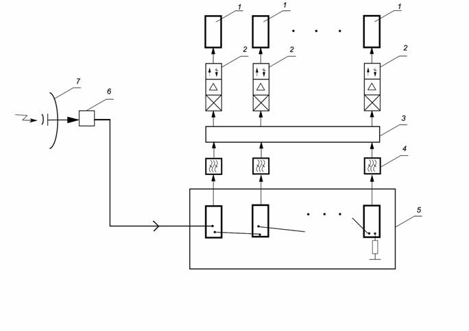
Fig.2
The block diagram (Fig. 2) includes the omnidirectional antenna 1, the powerful upconverter (BUC) 2, crossover N – channel 3, the channel bandpass filter (BPF) 4, the block from N – transmodulators with synchronization schemes with a support on signals GPS 5, low noise downconverter block (LNB) of receive RRS 6, and also the receive antenna of RRS 7.
The system works as follows. The multichannel group signal which for given BS is formed on CS and is transmitted by means of transmit RRS, is received by antenna receive RRS 7 and will be converted by means of the downconverter 6 to an intermediate frequency signal. Signal IF moves on a transmodulators block 5 inputs, in it separately for each of channels transition from modulation QPSK to modulation COFDM and symbols COFDM transmitting synchronization with the corresponding symbols transmitted by others BS in a network is carried out. In the channel correction block the received pilots-signals are analyzed. According to results of this analysis transfer function of a communication channel is defined and channel correction is carried out – the signal of everyone carrier is multiplied by value of the found transfer function for this carrier. In the following block it is carried out deinterleaving another (internal) interleaving and assembly – the operation opposite to decomposition of bits on symbols. As a result the sequence of bits which arrives further on the error correction block, similar to the corresponding block of the receiver of satellite digital TV turns out.
From transmodulators outputs IF signals which have passed through channel BPF, are deliver on powerful upconverters 2 (if frequency convertion is not required, and transmitting is carried out on the same frequency on which modulation in the transmodulators block, frequency converters change on power amplifiers is made). The give radio frequency signals radiate on air omnidirectional antennas 1. For the given variant basic novelty consists in use of frequency multiplexing in the propagation environment.
Referencies:
- The USA Patent - № 7583650, Sep.1, 2009, vol.1346, №1
- The USA Patent - 2004/0208590A1 Oct.21, 2004.
- The USA Patent - № 4211894 Jul.8, 1980, vol. 996, №2
The applicant, general director of Company "ROKS" Ksenzenko P. J.
The invention formula
The base station supporting on-air frequency multiplexing which includes the multiplexer connected to transmitters outputs and an antennas system input, differs that N – omnidirectional antennas are connected to N – transmitters in the form of powerful upconverters which are connected with N –channel crossover which is connected with N – bandpass filters which in the first variant are connected to single-channel optical receivers which are connected by means of N – channels fiber-optic lines to inputs N – optical receivers, and in the second variant N – bandpass filters are connected to block N – transmodulators with schemes of synchronization with a support on signals GPS which are connected with the low noise downconverter block (LNB) which is connected to antenna receive RRS.
The applicant, general director of Company "ROKS" Ksenzenko P. J.
ABSTRACT
Object of invention: Base station supporting on-air frequency multiplexing.
A scope: the Useful model concerns systems multichannel digital a television and audio broadcastings, including – in networks of a multichannel single frequency synchronous broadcasting (SFN).
An essence of useful model: The base station of a network a television and audio broadcastings includes N – omnidirectional antennas which are connected with N – transmitters in the form of powerful upconverters which are connected with a N –channel crossover which is connected with N – bandpass filters which in the first variant are connected with single-channel optical receivers connected through a N –channel fiber-optic line to N – optical transmitters outputs, and the power supply is connected with a N –channel crossover and with N - single-channel optical receivers, and in the second variant N – bandpass filters are connected to block of N – transmodulators with schemes of synchronization with a support on signals GPS which are connected with the low noise downconverter block (LNB) which is connected to receive RRS antenna.
Technical result: Provides essential increase in the service zone sizes at the expense of increase for each separate radio channel radiated power, and also at the expense of a multichannel single frequency synchronous broadcast network construction possibility gaining, in the centres of mutually overlapping cells which take places declared BSs. The declared system provides increase in efficiency of single-channel transmitters and possibility of simplification and reduction in base stations price because at IF signalling on separate veins of a multicore fiber-optic cable the synchronization system becomes simpler, decrease signal losses and the system noise stability raises. Besides, lighting protection becomes more reliable