Base Station Architecture Supporting on-air Frequency Multiplexing
Group and single-channel transmitters.
In modern digital TV broadcasting systems a transmitting over 100 TV programs is supposed. Most often used broadcast standards are DVB-T, DVB-C and DVB-S/S2.
For multi-channel signals transmitting group transmitters which will convert generated on IF multi-channel digital signal to a radio frequency group signal and gain it on power for transmitting on-air through single omni-directional antenna or the sector antenna if radiation is made in a zone limited to some sector can be used.
Much more attractive from the view point of a group signal formation convenience the method of its formation on intermediate frequency with the subsequent group spectrum conversion to a working radio frequencies range is represented.
The method alternative to the given, is single-channel transmitters application, each of which will convert and gain generated on IF the separate channel signal. The signals received from N single-channel transmitters multiplexing on a radio frequency are carried out by means of the special multiplexer consisting from N channel BPF (bandpass filters) and the same number ferrite circulators (Fig. 1).
Let's notice that both methods assume channels frequency multiplexing at physical level (PHY).
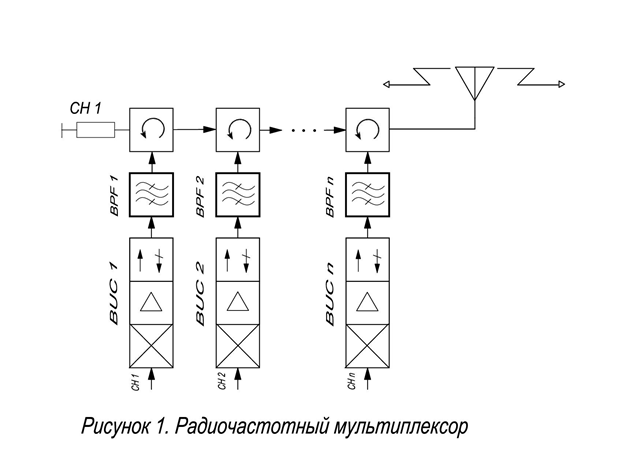
Fig.1 Radio frequency multiplexor
Let's consider the presented multiplexing methods merits and demerits from the view point of broadcasting complexes complexity and cost. For this purpose at first we will analyse the system consisting of the group transmitter and the omni-directional antenna.
Such structure unconditional advantage is its simplicity. It is clear that to generate a group signal on intermediate frequency much easier. However to realise such system it is possible no means always.
As it has already been told, the digital broadcasting can be carried out according to standards DVB-S/S2, DVB-T and DVB-C. In standard DVB-S (S2) systems each of channels represents carrier, modulated on method QPSK (8PSK), i. e. modulation methods with a constant envelope are used. As it is known, the modulation mode with a constant envelope is the most favourable from the view point of system power as for signal with modulation QPSK receiving it is enough to concern a signal / (noise + intermodulation) – SNIR at level 10-12 dB, and for 8PSK – SNIR = 19 dB.
At signalling of standard DVB-C modulation QAM64 (SNIR = 25 dB) more often is used. It is not less than on 13 dB above, than at QPSK.
At standard DVB-T (a modulation method COFDM) signalling on the foreground there is a factor showing the peak to average power rate of one transmitting signal throughout symbol – PAPR, average which value is equal 10 dB. It means that for not distorted symbol COFDM transfer the transmitter should have a power stock on 10 dB concerning a compression on 1 dB power (P1dB). Thus, standards DVB-C and DVB-T transmitter efficiency is approximately equal.
If to consider that the standard DVB-S/S2 transmitter can normally work at power level only on
3 dB low P1dB it is possible to draw a conclusion that for the same transmitter output 1 dB compression point power (P1dB) receiving for standard DVB-C or DVB-T transmitters power should be on 7 dB above, than standard DVB-S transmitters P1dB. We will assume for reasonings cleanliness that antennas of all three systems have identical gain factors. Then and EIRP (equivalent isotropic radiated power) which represent the transmitter output power in dBW and antenna gain factor in dB sum, will differ on the same 7dB.
Thus, the general prize in a radio line power at the expense of lower SNIR (on 13 dB) and more (on 7 dB) EIRP will make for DVB-S 13 + 7 = 20 дБ.
The truth in case the standard DVB-S transmitter is used as group it should possess the raised amplitude characteristic linearity level at which intermodulation products level will not exceed some set level (by transfer over 10 channels it is - 40 dBc). For such linearity achievement it is necessary that transmitter output power was approximately on 10 dB more low P1dB. Nevertheless, the prize and in this case will make 13 dB.
It is necessary to notice that group transmitter power calculation is made in the beginning concerning one channel, but taking into account requirements on the linearity, corresponding to a group signal transfer requirements. It would seem, for transmitter integrated power (PTOT) calculation, necessary for N channels gaining it is enough to increase the power defined for one channel (PCH) by channels quantity N, i. e. PTOT = PCH x N. In practice because a considerable quantity of not only 3rd but also higher orders intermodulation products occurrence which are the adjacent channels interaction consequence – intermodulation with the adjacent channels (ICI), the transmitter operating mode should be chosen even more linear that will lead to that P1dB, it will be essential to exceed PTOT.
The increase in a service zone radius demands with other things being equal to transmitter output power increase. At increase transmitter P1dB its cost increases much faster than power increases. Therefore for some output power value the group transmitter cost will be made even to cost N single-channel transmitters with output power PCH. At the further increase the group transmitter P1dB the single-channel transmitters application becomes more rational.
One more standard DVB-T feature is a single frequency television broadcast network application (Single Frequency Network – SFN) possibility in which the adjacent transmitters can conduct simultaneously broadcasting on carrier frequency synchronously transmitting the same multiplex, and receiving areas of their signals are blocked. In overlapping zones thanks to application COFDM presence of signals from two transmitters not only does not worsen reception quality, but on the contrary, presumes to improve reception at the expense of two signals powers addition. Use of a single frequency network allows to capture land TV-broadcasting the big territory, having distributed on it demanded quantity concerning low-power transmitters.
From the resulted reasons it is possible to draw such conclusions:
- Group transmitters are expedient for using in those systems in which modulation types with a constant envelope (standards DVB-S/S2) are used.
- At transfer by standards DVB-C and DVB-T group transmitter signals the channels quantity can be no more than 2-3. At much channels quantity them to use it is inexpedient because of their progressive increase P1dB.
- For the big territory coverage by rather low-power transmitters it is necessary to construction SFN resort.
The Method of on-air frequency multiplexing.
At broadcasting complexes designing very often there is a problem of a great number (from above 100) TV channels transfer in the limited frequencies band. Thus a service zone radius can make 50 Km and more. In one channel the multiplex from digital TV programs, including no more than 10 TV programs is usually transferred. For transfer 100 TV programs are necessary for using not less than 10 radio-frequency channels (radio trunks).
Single-channel transmitter application necessity as the group transmitter will be excessively difficult and expensive unequivocally follows from a task in view.
At a following design stage it is required to solve radio channels multiplexing way choice problem for the purpose on-air radiation of all signals obtained from single-channel transmitters. The multiplexer shown in Figure 1, is suitable for this purpose, but is expensive, and its manufacturing and adjustment are rather labour-consuming.
Besides, it brings big dissipative losses and demands introduction in structure of each channel path delay non-linearity compensator (equalizer) that is caused by presence at a path of the narrow-band filters which are the main phase distortions source. Therefore in declared system application of a frequency multiplexing method directly on air is offered.
On-air frequency multiplexing is a power addition in space method of the different frequency signals radiated by separate omni-directional antennas, each of which radiates a signal only one channel transmitter. All antennas are omnidirectional. Mutual antennas influence against each other which can deform their orientation diagram should be shown to a minimum.
Further the first variant of a similar complex realisation on an example of the MMDS Transmitting Complex in a range 5.705 – 5.825 GHz will be presented.
The short description
Initial data: The transmitting complex of MMDS in a range 5.705 – 5.825 GHz is intended for multi-programme (more than 100 TV programs) TV broadcasting within a service zone in radius more than 50 Km. The broadcasting should be conducted in standard DVB-T or DVB-C. Carrier quantity is 12. Thus, on one carrier it should be transmitted in one 10 TV programs multiplex of usual broadcasting quality SD. It is possible only at application of the digital compression MPEG-4 AVC (H.264) standard. A band occupied with one radio channel is up to 8 MHz. As all radio frequencies band is equal 120 MHz, the step of a frequencies grid between the next channels can be 10 MHz.
Calculation of system power: For the given design two rigid restrictions are characteristic:
- On a frequencies band (120 MHz);
- On an system energy potential which is limited, on the one hand, by use enough energy-wise ineffective modulations COFDM (PAPR = 10 дБ), and, on the other hand, necessity of a service zone covering having the considerable sizes (with radius more than 50 Km).
The transmitting complex will be established in a town on which suburbs one-storey building prevails. Therefore power calculation we will conduct for the propagation conditions close to line-of-sight (the easiest Ricean mode).
Let's take advantage of the formula recommended by the International Telecommunication Union (ITU).
It has such appearance:
10N*log d = PT (dBm) + GT (dB) + GR (dB) – 32.44 – PR (dBm) – 20 log f (MHz).
In the given formula:
PT = a transmitter output power (dBm);
GT = gain factor of the transmit antenna (dB);
GR = gain factor of the receive antenna (dB):
f = average working frequency of a radio channel (MHz).
Let's accept as initial following sizes:
- PT = 30 dBm;
- GT = 13 dB;
- GR = 30 dB;
- f = 5765 MHz.
At spectral density of thermal noise in the antenna – 174 dBm/Hz we will define a signal power on a receiver input in a band 8 MHz PR, necessary for confident reception, as the sum of the a necessary signal/noise rate (SNR = 25 dB) and a noise power on an input which consist of antenna noise in the channel band and the receiver noise factor led to an input (equal 3 dB):
PR = - 174дБм/Гц + 10 lg (8* 10 6 Гц) + 3 дБ + SNR = -174 + 69 + 3 + 25 = -77 дБм.
Factor N which is called “loss exponent” and characterises propagation conditions on a link we will choose from Table 1.
| Propagation conditions | Loss exponent |
|---|---|
| Free space | 2 |
| City conditions | 2.7-3.5 |
| City with dense many-storey building | 3 - 5 |
| Building directly on a beam course | 4 - 6 |
Using cited earlier given we will settle an invoice in the beginning for a mode line-of-sight in the pure state (N = 2).
20 log d = 30 +13 + 30 – 32.44 + 77 – 75.21 = 42.75.
From here d = 137 Km.
For the most easy mode in the conditions of a town (N = 2.7) we will give d = 38 Km.
Conclusion: for conditions line-of-sight power of 1W will be sufficient for a covering of a zone in 50 Km radius with some stock.
Let's be guided by power 30 dBm for one radio channel in width of 8 MHz.
We can consider two possible schemes of construction of the Transmitting Complex:
- With system application from four sector antennas, on each of which the individual transmitter is established. The transmitter should gain 12 - frequency group signal with total linear power 12 W (+41dBm). Because of appreciable intermodulation between the adjacent channels occurrence danger the stock on power of such transmitter should be much more than on 11 дБ (P1dB will be more than 300W, i. e. It is more 55 dBm).
- With application for each channel of the separate transmitter and the slot-hole omnidirectional antenna. Thus P1dB = 10 W (40 dBm).
The first variant should be rejected because of is inadmissible high value P1dB.
The second variant demands designing of antenna system construction and the new approach to the single-channel transmitter parameters estimation – Block Upconverter (BUC).
The antenna system can represent a two-storey construction. On each of floors six antennas in corners of a hexagon with the party 1м are established.
Each of six antennas not only radiates a transmitter signal but also receives the signals radiated by a number of located antennas. To estimate level of received signals it is reversible to the diagram in Fig. 2. The given diagram shows losses in space in a near zone around antennas which are resulted for two modes: a mode of line-of-sight (LOS) and a mode non line-of-sight (NLOS). The minimum losses in space (for mode LOS) on distance 1м make nearby 40 dB. To calculate, what level will be received on an antenna flange (directly on BUC output), it is necessary to subtract from this size gain factors of two antennas (transmit and receive) in dB, i.e. 13 + 13 = 26 dB. Thus, the signal received by the antenna will be on 40 – 26 = 14 dB less, than a signal radiated by it. The antenna co-operates not with one, and with five antennas which are settling down on the given floor. Between the antennas located on different floors, it is possible to neglect communication because the narrow diagram of antennas orientation in a vertical plane. Considering that fact that each of antennas will receive signals from five nearby antennas two of which will defend from it on 1m, and three more – approximately on 2.0 m, we will reduce losses on 4 dB. We will definitively receive that the size of a signal accepted by everyone antenna will be only on 14 – 4 = 10 dB less level of a signal which it radiates. This signal is perceived by the terminal transmitter cascade as the signal reflected from load (as at high VSWR of load) and can cause unstable work of the amplifier.
If the hexagon party in which tops antennas are placed to increase, for example, to 2m level of received power will decrease to – 16 dB. Thus dimensions of antenna system considerably will increase. It is visible that increase in the linear sizes ineffectively. It will be much more effective application of the ferrite gate which can provide an outcome 20 dB and more. Thus matched load of the gate should dissipate constant power not less than 100 mW.
Certainly, such calculation has estimated character and shows only the tendency of antennas interaction in system. Character of antennas interaction depends not only on distance between them, but also from their design and the sizes, and also from wavelength. At interaction in a near antennas diagram of an orientation zone can be deformed, and already it is impossible to consider their gain factors as constants. For certain type antennas mathematical models of interaction in a near zone which will yield more exact result can be created and will allow to choosing the most optimum design of antenna system.
The second method of an interconnection between antennas reduction is diversity them on a vertical. Thus because of a considerable quantity of antennas the vertical size of such antenna system will be big, shadowing from a mast construction on one of radiation direction is considerable. There can be difficulties in system service. In any case the antenna design is a compromise between shadowing and reflections possibility occurrence from outside constructions of a tower and power losses of a signal in the antennas located in the same plane.
As all transmitters (all 12) work on different frequencies, but in one frequencies band all of them radiate extra band noise and disturbances local oscillator signals and image frequencies which are integrated in the given band. Total all these signals power which is radiated by 12 transmitters, will be accordingly on 11 dB more than the power of parasitic signals radiated by one transmitter. Thus, we will be compelled to toughen requirements on parasitic radiations value for each transmitter on the same 11 dB.
The block diagram of the Transmitting Complex is shown in Fig. 3. The equipment most part here is placed in a water-proof case which is completed by the thermostat and fan system. The signal received from the optical receiver (which also can be placed in a case) represents a group multi-channel signal in which channels can settle down any way in a frequencies range.
The power division of an input signal between Processors is made by means of loop back inputs of Processors in which the signal part branches off in the corresponding Processor, and other signal arrives on an input of the following Processor. Thus signal losses make 1.5 dB on each connection. That the difference in levels of signals on an input of the first and on an output of 12th Processor would not differ strongly (on 18 dB), the signal preliminary divides on two equal parts with the help of splitter, and then arrives on groups of 9 Processors.
Thus differences in levels decrease to 9 dB. So we save a stock on adjustment for the input scheme of an ALC. From outputs of Processors signals arrive on BPF with which help the channel filtration in an 8 MHz band is carried out that allows to reduce level of extra band interferences and noise.
Power supply on BUC moves on radio-frequency cables. Injecting of supply voltage in all 12 cables is made in the Crossover.
In table 2 advantages and lacks of the given architecture are specified.
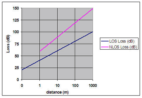 fig.2 Losses on a line in a mode of "line-of-sight» (LOS) and «non line-of-sight» (NLOS).
The given signal should be processed by firm Televes Processors UHW. With their help channels are grouped in frequency in a certain order with a step of 10 MHz.
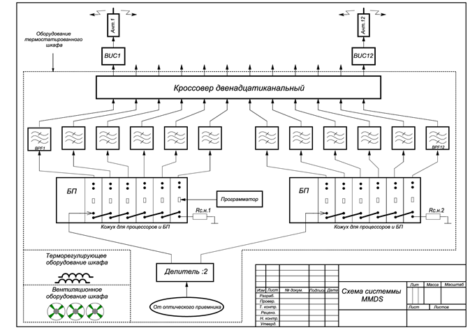
Fig. 3 The basic architecture of MMDS Transmitting Complex.
From Table 2 follows that to some parameters BUC increased requirements are shown. They are caused by two factors:
- Application of modulation COFDM;
- Coupling of antennas in system and features of signalling mode.
Table 2. Advantages and lacks of the chosen Transmitting Complex architecture.
| Advantages | Lacks |
| Use concerning low-power transmitters. | Quantity of transmitters to equally quantity of radio channels (12). |
|
Narrow-band slot-hole antennas have at Ku = 13 dB small dimensions. |
It is difficult to avoid distortions of the antenna orientation diagram in antenna system because of a difficult design of antenna system. |
| Rational use of frequencies band. | The quantity of the coaxial cables connecting equipment ODU and IDU is equal to quantity of transmitters (12). |
| Possibility of a power supply giving on transmitters ODU on radio-frequency cables. | Necessity reliable shielding of coaxial cables from each other and from sources of external disturbances (TV UHF transmitters, GSM base stations etc.). |
| A minimum quantity of the equipment which should be established at tower top. | Increased requirements to some parameters of transmitters which are caused by interaction of antennas and other features of system work. Parameters to which requirements are raised:
|
Modulation COFDM in itself demands performance of some especial requirements.
These are such requirements:
- Suppression of image frequencies – not less than 60 dBc.
- Phase noise level of local oscillators at retune from carrier on 10 KHz – no more – 95 dBc/Hz.
- The stock on power concerning a power average level – not less than 10 dB (PAPR = 10 дБ).
The requirements caused by features of antenna system work the following:
- Noise power, disturbances, and parasitic products (ingress noise) – at level -11 дБ from their level for a case of one transmitter and one antenna use.
- Power the local oscillator on an input is equal to power of the usual transmitter a minus 11 dB.
The Block diagram of declared system (the Variant 1).
The tentative estimation of a 12 single-channel transmitters BUC1 – BUC12 total cost with output power PCH = 1W shows that this cost more low, than cost of the group transmitter with output power P1dB = 300 W. Therefore point 1 in section of Table 2 "lacks" becomes one of advantages.
The lacks concerning points 3 and 4 are essential, and for their overcoming in the scheme resulted earlier it is necessary to incur considerable expenses. Therefore in the declared device it is offered to refuse signalling of separate channels on IF on coaxial cables. Instead it is offered to apply the multi-core fibre-optical cable which quantity of veins corresponds to quantity of channels N.
The block diagram of declared system is shown in Figure 4. The design of an equipment radio-frequency part and its elements remains without changes in relation to shown on Fig. 3. In the device are applied N omni-directional antennas (ANT1 – ANTn), N transmitters in the form of powerful upconverters (BUC1 – BUCn) p. 2, crossover N – channels p. 3 and N bandpass filters (BPF1 – BPFn) p. 4. On it similarity to earlier resulted scheme comes to an end.
Other part of a complex works as follows:
Signals of separate channels on IF having modulation QAM64 (DVB-C) or COFDM (DVB-T), arrive on inputs N of optical transmitters p. 7. Here they will be converted to an optical range and transferred on separate veins of a fibre-optical cable p. 6,
Which connects a studio part of a complex to that its part which is placed at tower top (in an installation site of a radio-frequency part). This part begins with single-channel optical receivers p.5 which will convert optical signals back to signals IF.
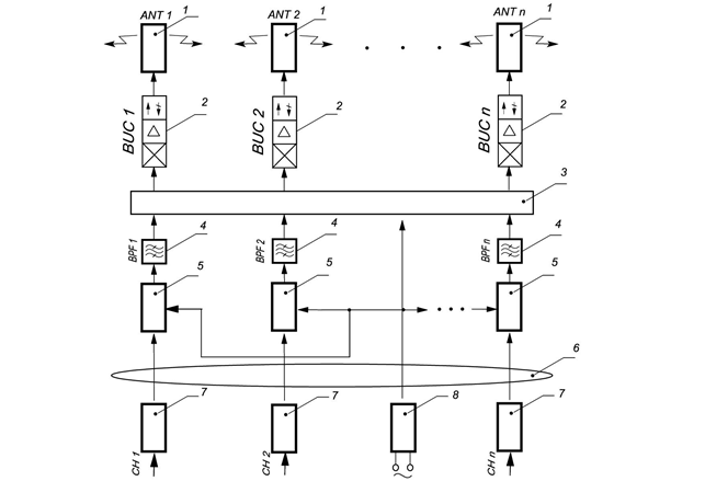 Fig.4
Fig.4
At the expense of signalling on a fibre-optical line all problems connected with a signal losses will be removed and also high noise immunity is reached. The distance on which the signal on fibre- optic cable can be transmitted, can reach 15 Km and more.
Thus, the main differences of declared system from existing will be the following:
- Use of single-channel transmitters signals frequency multiplexing method in the transmitting space (on-air) by means of omni-directional antennas system.
- Separate channels signalling from a complex studio part to its part placed at tower top, by means of the multi-core fibre-optic cable including in the design a conductor, serving for supply voltage giving from the power supply unit 8 on a complex radio-frequency part and optical receivers. Such construction allows to signals transmit on the big distances and excludes accumulation of noise and intermodulation products on fibre-optic cable line.
- Signalling on the big distances possibility reached at the fiber optic cable use and maintenance thus high noise immunity in the industrial disturbances conditions allow to construct on the given Base stations basis a single frequency synchronous broadcast network (SFN) for each of multiplexing in the propagation space channels.
Thus signals from the network Central station (the Studio complex) are transmit to network Base stations on fibre-optic cables that allow to constructing a single frequency synchronous broadcast network for each of channels.
Besides, as delays by transfer on fibre-optic cable on distances of several tens in Km are very small and can be in advance defined, and the reflected signals are absent, the all network synchronisation is reached at the Central station by delay dispersion correction in each of channels. At the big network sizes it can give the big economic benefit as the corrector quantity will be minimal.
The declared system block diagram (the Variant 2).
The base station block diagram variant 2 assumes use in networks in which for any reasons fibre-optic cable lining for the Central station with Base stations set connection is impossible. In such networks instead of fibre-optic cable it is possible to use simplex radio relay communication lines (RRL). By multi-channel group signal transfer on RRL the frequency multiplexing, but reached on PHY level, also is used. Signalling on RRL and an broadcast Base stations is made with use of various standards (DVB-S – on RRL and DVB-T – for broadcast Base stations), therefore in signals processing paths it is necessary to establish the transmodulators QPSK/COFDM block (5 in Fig. 5) in which transport streams processing is supposed. Therefore synchronisation SFN in each channel should be made already at Base stations, and at the Central station pilot-signals are entered.
Designations on the block diagram:
- The slot-hole omnidirectional antenna.
- The Powerful Upconverter (BUC).
- Crossover N – channels.
- The channel bandpass filter (BPF).
- The Block from N transmodulators with synchronisation schemes and with a support on signals GPS.
The system works as follows. The multi-channel group signal which for the given Base station is formed by the Central station, is received by receive RRS antenna 7 and will be converted by the downconverter 6 in an intermediate frequency group signal. Signal IF moves on the transmodulators block 5 inputs. In it separately for each channel transition from modulation QPSK to modulation COFDM and synchronisation with corresponding symbols COFDM transmitting by other Base stations in a network is carried out.
In the channel correction block the accepted pilot-signals are analyzed. By this analysis results a communication channel transfer function is estimated. Then channel correction is carried out – everyone carrier signal is multiplied by the found channel transfer function value for this carrier. In the following block the second (internal) interleaving and assemblage deinterleaving are carried out – operation, return to bits apportion on symbols. The bits sequence which arrives further on the errors correction block, similar to the corresponding block of satellite digital TV receiver as a result turns out.
From transmodulators outputs the IF signals, having passed channel BPF, move on powerful upconverters 2 (if frequency conversion is not required also transfer it is carried out on the same frequency on which modulation in the transmodulators block is made, frequency converters are replaced with power amplifiers). The gained radio frequency signals are radiated in an air by omni-directional antennas 1.
For the given variant basic novelty consists only in frequency multiplexing in the transfer space application.
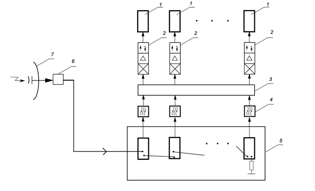 Fig.5
Fig.5
Gained effect: The general system cost decrease, reliability increase and high noise immunity achievement.
Authors

Petro Himich
Engineer. Team Leader for Company "ROKS"