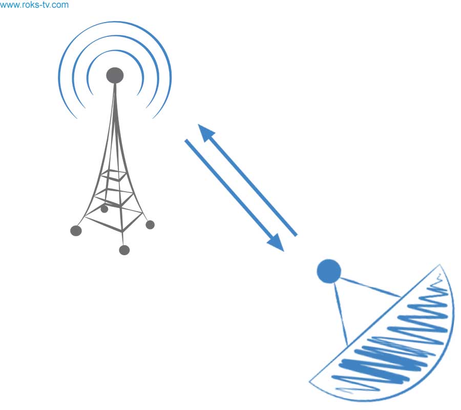
INTERACTIVE WIRELESS SYSTEMS
1. Structure of the minimum set of equipment for prototypes of multiservice system MITRIS-MEDIA code ААБШ.464423.120.
The set of equipment of multiservice system MITRIS-MEDIA code ААБШ.464423.120 contains the following basic elements:
1. The station MITRIS-MEDIA (BH) or MITRIS-MEDIA (BL) ААБШ.464423.121 radio-frequency Unit having two options of execution depending on those, in even or odd sector it has to be established. At the first stage it is possible to be limited to one sector and one option of execution – MITRIS-MEDIA (BL).
2. The subscriber station MITRIS-MEDIA (AH) or MITRIS-MEDIA (AL) ААБШ.464423.122. Execution options also depend on that, in even or odd sector this subscriber station will work. At this stage it is possible to be limited to option of execution MITRIS-MEDIA (AL). For subscriber station work research as a part of a data transmission network it is necessary to make 10 samples of subscriber stations of this type.
2. Basic principles of the system construction.
At system development the technical solutions protected by Ukrainian Patents No. 54643 and No. 54644 were used.
The system of MITRIS-MEDIA (B) represents the radio-frequency Unit of MITRIS-MEDIA system Base station intended for transfer and reception of downstream and upstream data in a station service zone which has a circle form with a radius up to 2 Km. In this zone the MITRIS-MEDIA (A) subscriber stations, which can receive downstream signals and transmit upstream signals, can be located.
The radio-frequency Unit of the MITRIS-MEDIA (B) Central station (CS) represents system from 4 or 8 pairs of sector antennas with vertical and horizontal polarization which are intended for downstream and upstream signals transfer and reception. Subscriber stations like MITRIS-MEDIA (A), belonging to one sector, in the return channel can work at several frequencies appropriated to this sector (FDMA mode), and also in a mode of time division (TDMA) or code division (CDMA) multiple access. In the downstream channel the mode of time multiplexing (TDM) is used. In the next sectors for direct channels different frequencies also are used. In opposite sectors it is possible to use identical frequencies. Thus, for formation of the frequencies plan for all sectors it is enough to have only two frequencies sets for the downstream and upstream channels. Pair frequencies strips of reception and the transfers intended respectively for even and odd sectors are shown in Figure 1. This system can serve only those subscribers for which in strict sense of the word conditions of "direct visibility" between CS and any of subscriber stations are satisfied.
The absence of reflected signals when subscriber stations receive signals in the "line of sight" mode of the Central station, also a high degree of directivity of parabolic-dish antenna of subscriber stations allow you to use spectrally-efficient modulation methods up to 256QAM for data transmission via the direct channel. A large throughput of DOCSIS 3.0 modems allows you to transmit both information signals and digital TV signals in a single digital stream.
3. Frequency plans.
The system works in two frequencies bands:
12.75 – 13.25 GHz – downstream signaling (the frequency plan is shown in Figure 1 above)
10.15 – 10.65 GHz – transfer of the upstream channels (the frequency plan is shown in Figure 1 below).
Each of these frequencies bands is divided into two strips 150 MHz wide, the protection interval between them is equal 200 MHz. For creation of prototypes it is offered to use for transfer only a strip of 12.75 – 12.9 GHz, and for reception – 10.15 – 10.3 GHz.
Division into two strips is caused by need of frequency division by transfer of the upstream channels in the next sectors therefore the bottom range is intended for transfer in odd sectors, and top – in even. Total quantity of sectors always is the even number.
4. Radio-frequency Unit of the Central station MITRIS-MEDIA (B).
In Figure 1 the block diagram of one sector of the MITRIS-MEDIA (B) Central station Radio-frequency Unit is shown.
Signals of downstream channels are transmitted in a strip of 150 MHz by means of the sector antenna with a beamwidth 90 degree and vertical polarization. Reception of upstream channels arriving from subscribers which take place within this sector is carried out by means of other similar antenna but with horizontal polarization. From reception side the bandpass filter with a bandwidth of 10.15-10.3 GHz is installed.
Signals of upstream channels are generated by linear DOCSIS 3.0 cards at an intermediate frequency in the range of 700-850 MHz. After that they will be converted in BUC to radio frequency signals in the range of 12.75-12.9 GHz, amplified on power and by means of the transmitting antenna are radiated in sector in the form of a beam of 90 deg. wide.
The signals of upstream channels that arriving from the MITRIS-MEDIA (A) subscriber stations are received by other sector antenna, pass through the filter with a band of 10.15-10.3 GHz, and reach the LNB. After that the signal of intermediate frequency with a band of 1300-1450 MHz reaches the converter block in which it will be converted to frequencies in a band of 14-65 MHz (which can be received by CMTS).
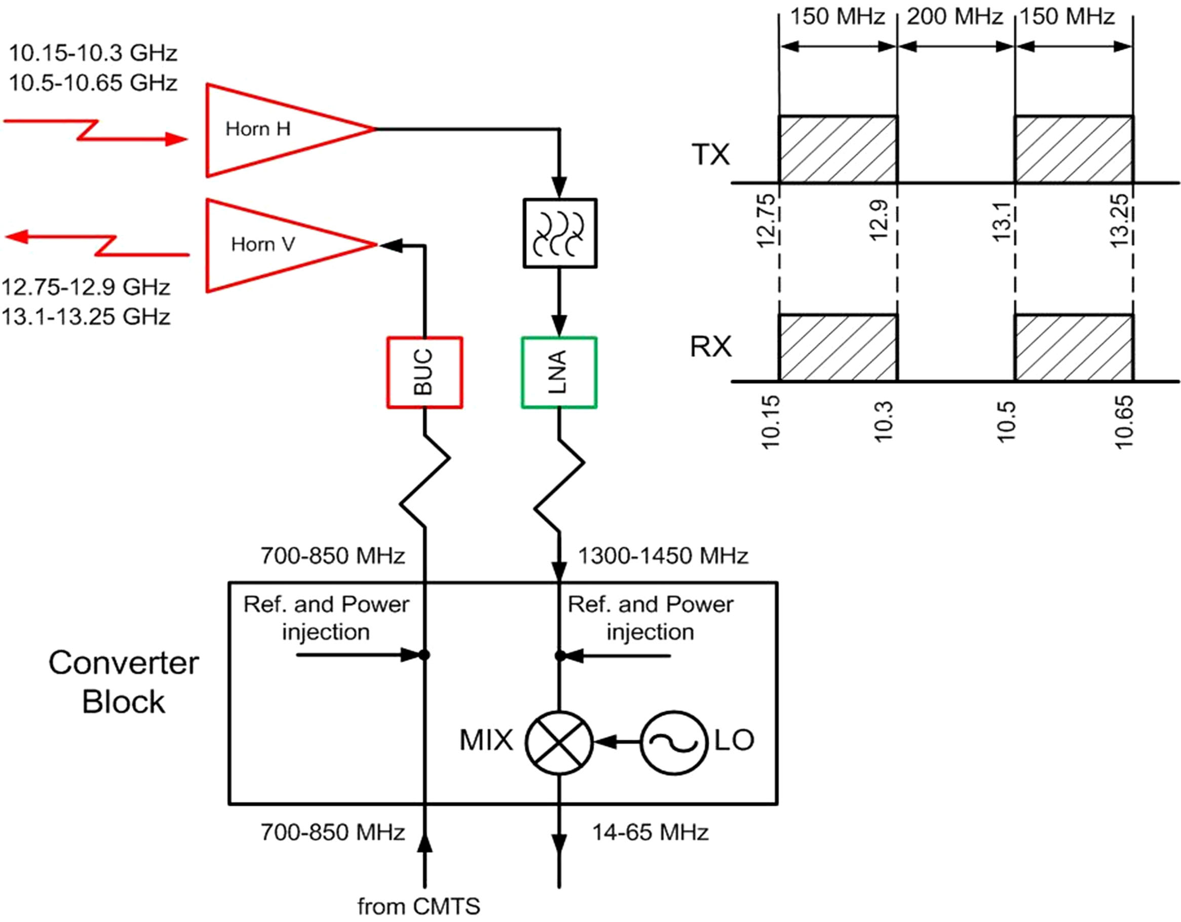
Figure1. Block diagram of central station radio-frequency unit one sector
5. Subscriber station MITRIS-MEDIA (A).
Subscriber station MITRIS-MEDIA (A) (see. Figure 2) consists of three main parts:
- integrated from an antenna transmit-receive microwave head (iLNB) of external execution;
- the transceiver – the internal block;
- subscriber modem (CPE) of the DOCSIS standard.
The receiving part of a transmit-receive microwave head serves for downstream signals reception in a band of 12.75-12.9 GHz or 13.1-13.25 GHz and their convertions down on frequency in the range of the intermediate frequencies of 1.8-1.95 GHz; and transmitting part – for upconvertion on the frequency of the signal which is settling down in a band of the intermediate frequencies of 650-800 MHz in bands of the frequencies of 10.15-10.3 GHz or 10.5-10.65 GHz (which it is used for transfer on air of the upstream channels). For this purpose the microwave head (iLNB) has two options of execution depending on local oscillator frequency. For the purpose of the maximum decrease in weight, dimensions, and the cost of a transmit-receive microwave head in its structure the common local oscillator for receive and transmit parts with a frequency of 10.95 GHz or 11.3 GHz is used. At this development stage creation of 10 prototypes with a local oscillator frequency 10.95 GHz is supposed.
The transmit-receive microwave head connects to the block of converters (transceiver) by means of two coaxial cables with the small losses intended for the radio-frequency signals transfer and the third cable on which signals of iLNB power amplifier switching off in transfer pauses are transmitted. Converted in iLNB signal arrives on the transceiver block which has internal execution. The signal passes the frequency converter in which it will be converted to a signal with a frequency suitable for reception by the subscriber modem (CPE). The transceiver connects to CPE by means of the duplexer dividing signals of downstream and upstream channels.
The signal of the return channel on IF 14-42 MHz from CPE through a duplexer arrives on the first upconverter by means of which it will be upconverted on frequency to the fixed frequency 1700 +/-14 MHz on which are filtered by two SAW BPFs which are divided by the amplifier. Further this signal will be converted down to one of frequencies in a band of 650-800 MHz and reaches transmitting part of the transmit-receive microwave head. In the transmitting part of a microwave head this signal will convert to one of frequencies in a band of upstream channel transfer 10.15-10.3 GHz or 10.5-10.65 GHz and amplify on power.
Feature of subscriber station architecture is that because of top in relation to an output signal of transmitting part of iLNB a local oscillator arrangement there is an inversion of a transmitting signal spectra. In order that iLNB radiated not inverted signal (the DOCSIS standard doesn't allow spectra inversion), it is necessary that in the converter local oscillator frequency was chosen so that inversion of a spectra happened one more time. This inversion is made by the second converter of the transceiver transmitting part.
The iLNB antenna has two options of execution:
1. In the form of the two-reflector antenna (Cassegrain);
2. In the form of the horn antenna.
The antenna having a main reflector with a diameter of 60 cm is intended for those subscriber stations which are placed at long distances from CS and horn antennas are used at a placement of subscriber stations at small distances from CS. The supply voltage on iLNB moves by the radio-frequency cable connecting the transceiver with reception part of iLNB; and a signal of the reference oscillator moves by the radio-frequency cable connecting the transceiver with transmitting part of iLNB. In one more coaxial cable the signal of transmitter switching off in pauses between slots transfer. In pauses there is a shutdown of power supply of the power amplifier.
.jpg)
Figure 2. Block diagram of the subscriber station MITRIS-MEDIA (A)
Table 1. Key parameters of transceiver microwave head
| The parameter name, a unit of measure | Value |
|---|---|
| Receiver input working frequencies range, GHz | 12.75-12.9; 13.1-13.25 |
| Receiver output working frequencies range, GHz | 1.8-1.95 |
| Transmitter input frequencies range, MHz | 650-800 |
| Transmitter output frequencies range, GHz | 10.15-10.3; 10.5-10.65 |
| Receiver noise figure, dB | 4 |
| Dynamic range upper bound at the receiver output, dBm, not less | -30 |
| Receiver gain factor (without adjustment), dB, not less | +30 |
| The attenuation realized by two filters in front of the mixer in the receiver at transmitter frequencies, dB, not less | 65 |
| The attenuation achieved by LPF of the receiver at transmitter frequencies, dB, not less | 40 |
| Receiver selectivity of image channel, dB, not less | 50 |
| Cross polarization outcome in polarization selector, dB, not less | 20 |
| Local oscillator frequency, MHz | 10950; 11300 |
| Local oscillator frequency instability (is defined by a reference signal), ppm | +/- 0.5 |
| Local oscillator phase noise, dBc/Hz, at detuning from carrier on 10 kHz | -85 |
| IRF parameters of transmitter | |
| Working frequencies range, GHz | 10.15-10.3; 10.5-10.65 |
| Local oscillator suppression at output concerning useful signal level, dBc, not less | 60 |
| Image suppression concerning useful signal level, dBc, not less | 50 |
| Output receiver dynamic range, dBm | -40...0 |
| Input transmitter dynamic range, dBm | - 30...-10 |
| Transmitter nominal output level, dBm | +20 |
| Transmitter gain factor (without adjustment), dB | 50 |
| Adjustment range in the transmitter and receiver, the dB, not less | 34 |
| Reference signal level at transmitter input, dBm | -10...0 |
| Antenna parameters | |
| Gain factor, dBi: | |
| Option 1 (Cassegrain) | 33 |
| Option 2 (Horn) | 13 |
Table 2. Transceiver of MITRIS-MEDIA (A) Subscriber station
| External characteristics of the device | |
|---|---|
| Input downstream receiver frequencies range, MHz | 1800–1950 |
| Input CPE frequencies range, MHz | 14-42 |
| Output upstream transmitter frequencies range, MHz | 650-800 |
| Frequency deviation from nominal value, kHz, no more | 5 |
| Admissible signal levels range at downstream receiver input, dBm | -40...-10 |
| Admissible signal levels range at upstream transmitter output, dBm | -30...0 |
| Downstream channel bandwidth, MHz | 28 |
| Admissible signal levels range at downstream channel output, dBuV | 43...73 |
| Upstream channel frequencies bandwidth, MHz | 28 |
| Admissible signal levels range at upstream transmitter input, dBuV | 68...114 |
| VSWR at input and output for iLNB connection | 1.5 |
| Gain flatness at the upstream channel transmitter output in a band +/-14 MHz at local oscillator retuning, dB, no more | 1.8 |
| Gain ripple on the downstream channel receiver output in band 28 MHz, dB, no more | 0.5 |
| Group delay flatness at downstream channel receiver output in a band 28 MHz, ns, no more | 60 |
| Group delay flatness at upstream channel transmitter output in a band 28 MHz, ns, no more | 60 |
| Own noise and interference at downstream channel receiver output in band of 350 – 500 MHz, dBm, no more | -70 |
| Own noise and hindrances at upstream channel transmitter output in band +/- 14 MHz, dBm, no more | -80 |
| Upstream transmitter second local oscillator level at output, dBm, no more | -80 |
| Reference oscillator frequency, MHz | 10 |
| Reference oscillator relative instability in the interval of temperatures 0 …+40 deg. C, ppm | +/- 0.5 |
| Reference oscillator phase noise, dBc/Hz at carrier detuning: | |
| 100 Hz | -135 |
| 1 kHz | -143 |
| 10 kHz | -145 |
| Range of reference oscillator admissible levels at the external iLNB connection output, dBm | -5...+5 |
| Power supply Voltage for iLNB, VDC | +15 |
| Current consumption, mA, no more: | |
| Transmit part of iLNB | 800 |
| Receive part of iLNB | 270 |
| Parameters of electromagnetic compatibility | |
| Upstream transmitter signal 650 – 800 MHz suppression in downstream receiver working band at receiver output, dB, not less | 80 |
| LPF cut frequency of reference oscillator, MHz | 10.7 |
| Parameters of duplexer (EuroDOCSIS) | |
| The cut frequency of downstream receiver output HPF, MHz | 88 |
| The attenuation brought by HPF at frequencies of 14 - 42 MHz, dB, not less | 50 |
| LPF cut frequency of upstream transmitter input, MHz | 65 |
| The attenuation achieved by LPF at frequencies above 100 MHz, not less | 48 |
| Parameters of receiver | |
| The signal with frequencies of 650 – 800 MHz suppression size by input BPF in relation to level of a downstream signal, dBc, not less | 60 |
| IMD3 level at the receiver output for input signal level -10 dBm and output level 73 dBuV (through transfer factor is -10 dB) in relation to level of a useful signal, dB, no more | -50 |
| Local oscillator phase noise, dBc/Hz, no more at detuning from carrier: | |
| 100 Hz | -80 |
| 1 KHz | -87 |
| 10 KHz | -90 |
| Receiver noise figure, dB, no more | 7 |
| Through transfer factor retuning limits, dB | -26...+4 |
| Parameters of Transmitter | |
| Local oscillators suppression level at output in relation to useful signal level, dBc, not less | 60 |
| Image channel suppression level at output in relation to useful signal level, dBc, not less | 60 |
| IMD3 at input signal level 114 dBuV and output level is 0 dBm (through transfer factor is -5 dB), dBc, no more | -40 |
| Phase noise of the first (fixed) local oscillator, dBc/Hz, no more at detuning from the carrier: | |
| 100 Hz | -85 |
| 1KHz | -92 |
| 10 KHz | -95 |
| Phase noise of the second (retuned) local oscillator at retuning within 2350 – 2500 MHz, dBc/Hz, no more at detuning from the central frequency: | |
| 100 Hz | -80 |
| 1 KHz | -87 |
| 10 KHz | -90 |
| Step of transmitter frequency retuning, MHz | 1.0 |
| The through transfer factor retuning limits, dB | -5...+25 |
The transceiver microwave head (iLNB) has the design assuming its outdoor work in severe climatic conditions. The transceiver is installed indoors near the cable DOCSIS modem and connects to it two cables.
Authors

P. Y. Ksionzenko
CEO of ROKS

Petro Himich
Engineer. Team Leader for Company "ROKS"