UWMS-R as Advanced UWMS that Assigns for Working in Heavy Rain Regions
Abstract
Expansion of a user’s stations receivers dynamic range at the expense of their gain factors adjustment and introduction of user’s stations receivers RF paths monitoring in system MVDDS carried out with use of direct and return data transmission own wireless network channels.
The required dynamic range of Central (Base) station receivers reduction by posts of video information gathering transmitters output level control with using the own wireless data transfer network downlink and uplink channels.
A scope
The given technical decision concerns radio engineering, more precisely, - to a broadcasting, to a video information gathering (video surveillance) and data transmission in borders of a certain geographical zone on district. System UWMS which is a prototype of patented system UWMS-R (“Rain”) represents a version of system MVDDS which is added by a video information gathering system. In it range Ku is mainly used. For example, for downlink the occupied frequencies band is equal 800 MHz. The band for uplink and a video information gathering system also can reach to 800 MHz. These bands shouldn't be blocked with each other. On the contrary, between them some gleam is desirable. Range Ku is lowest of frequencies range in which allocation enough wide frequencies bands for direct broadcasting and data transmission channels, and also for return data links and video information gathering system channels is still possible. The given ranges it is used by systems MVDDS on a secondary basis as all of them or their considerable parts coincide with system DBS working ranges. These frequency ranges is boundary from the point of view of losses in hydrometeors as on frequencies above 10 GHz growth of a radio signal propagation losses to a rain zone (see Fig. 1) begins. Presence of the big losses in hydrometeors demands from direct and return receivers channels the expanded dynamic range on received signals levels for which achievement in system special measures should be taken.
Absorption in a rain
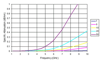
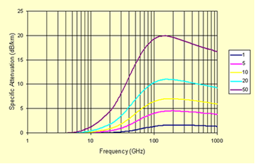
From Figs. 1a and 1b it is clearly visible that losses of a signal at the expense of absorption in a rain strongly depend on frequency. On frequencies below 5 GHz these losses in most cases can be neglected. But on the fixed communication and broadcasting lines working on frequencies above 20 GHz losses in a rain become a primary factor limiting the communication distance.
Naturally, losses in a rain depend on its intensity. In a zone of intensive rains on the foreground there is a peak intensity of a rain which is observed duration 0.1 % of time that corresponds to usual value of a line readiness 99.9 %.
It is much more important than the general annual norm of deposits. Peak intensity strongly depends on a geographical zone. In droughty regions intensity of a rain can to make some mm at hour (zones of violet color in Fig. 1с). In regions with very intensive deposits peak values of intensity can reach to 150 mm/hour (red zones in Fig. 1с correspond to intensity of 40 mm/hour and above).
ITU recommends methods for an exact prediction of losses in a rain. We will try to make rough calculation on the basis of materials available in the literature for a likelihood component of signal attenuation in deposits. All calculations for communication systems can be conducted taking into account hourly average distributions of rains intensity for the worst month of year.
a)
b)
Fig. 1 Dependence of loss factor γ on frequency: a) for frequencies below 10 GHz; b)for frequencies above 10 GHz.
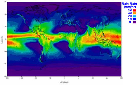
Fig. 1с A parity of loss factors for various geographical regions (source ITU-R).
The loss value at absorption of a radio signal by hydrometeors in dB is defined under the formula:
V=-y*Ref
where:
γ- loss factor, dB/Km,
Ref -effective length of a line (Km) on which the loss factor is approximately constant and equal γ.
From Fig. 1b we find that the loss factor on frequency 11 GHz for region with deposits intensity of 50 mm/hour is equal about 2 dB/Km. It means that the stock on loss in rain on a line of 15 Km should be equal 30 dB.
Fig. 1b also convincingly shows that application of broadcasting and data transmission systems working on higher frequencies than applied in patented system in regions with such amount of precipitation in general is impossible.
Other factors influencing on input dynamic range of receivers used in system.
Output power level of Central Station each sector transmitter has the fixed value. This value gets out from a calculation of the minimum necessary signal/noise rate (SNR) maintenance for the most remote station of the subscriber under the worst reception conditions.
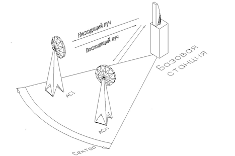
Fig.2 «Point–to-multipoint» network structure with spatial channels division on sectors within a service zone.
UWMS-R is fixed communication system, i.e. position in space of all subscriber’s stations concerning the system Central (Base) Station (CS) is in advance known. We will assume that the radius of CS service zone is equal 15 Km (r3 in Fig. 3), and most near placed subscriber’s stations are placing from CS on distance of 150 m (r1 in Fig. 3). Then the relation of lines lengths of distribution for the station which are on the brink of a service zone, and station which is from CS on distance only 150 m, will make 100:1. Expressed in dB the relation of received signals powers for these stations will be equal 54 dB (almost a mode to "direct visibility», but taking into account the city propagation environment). This dynamic range component on receiver’s inputs is a constant and practically doesn't depend on time. If to consider losses in a rain which are a variable component of a dynamic range accepted by user's stations and the Central station of signals possible difference in power levels on user's stations receivers inputs and video information gathering system CS receivers inputs will reach 84 dB.
The method which is used for increase in a dynamic range on a receiver input more often is application AGC in the receiver. As receivers in a broadcasting part of user's station and in a CS video information gathering subsystem the standard tuners (set-top box) standard DVB-S are applied in systems DBS. The range of admissible signals levels on tuner DBS input at work in a land broadcasting system is usually equal from – 50 dBm to – 20 dBm that corresponds to AGC depth nearby 30 dB. Some reduction of adjustment depth in AGC scheme rather 40 dB which correspond to receiving of satellite broadcasting channels speaks higher level of own land broadcasting systems receivers noise concerning noise in systems DBS because of what the bottom level of an adjustment range raises approximately on 10 dB, and the adjustment range decreases to 30 dB. But it is obviously not enough this AGC range for full indemnification of all receiver input signal level range, which as it has already been told, can reach 84 dB.
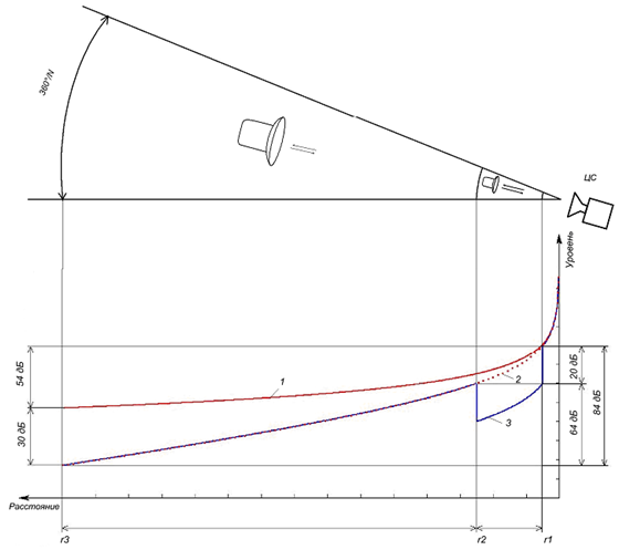
Fig.3 A necessary user’s receivers dynamic range determination.
A dynamic range expansion on a receiver input in UWMS-R.
In UWMS-R for partial indemnification of such big difference in received signals levels which is peculiar both to receivers of user's stations, and concerning to CS to a video information gathering system receivers the method of a user’s stations parabolic antennas corresponding gain factors choice (diameters of mirrors), and user’s stations transmit and receive microwave converters and video information gathering posts transceivers microwave transmitting converters gain factors can be applied. Such adjustment is carried out in transmit/receive microwave heads of user's stations and can be realized at the expense of the additional AGC loop covering high-frequency cascades of receivers. AGC Voltage simultaneously can be used and for adjustment on the same value the transmit/receive heads transmitting parts gain factors that is possible thanks to similarity of channels of reception and transfer. Such method is simple enough, but has essential lacks. The reception part of microwave transmit-receive head accepts not only broadcasting signals, but also a signal of a direct information channel (downlink). At gain factor adjustment the priority should be given signals of a television broadcasting as they demand transfer to a mode of real time, and admissible at their reception errors factor on two order more low than required for correct reception of an information channel signals (10-8 against 10-6).
If all adjustment in broadcasting channels to concentrate in user's station it will be impossible to supervise quality of broadcasting signals reception by it operatively, being on CS. At the same time, one of important MAC components in modem WMTS is the quality management program (QoS) which allows to control by work of data transmission network flexibly. The similar system is necessary and for broadcasting channels.
The second lack peculiar to gain adjustment which is completely concentrated in user's station, is very big complexity and duration of all system installation process. It will be necessary to establish threshold values for AGC in each of transmit/receive microwave heads individually taking into account a distance to CS that at a considerable quantity of subscribers a lot of time will demand. In the absence of all system work monitoring on CS it is impossible to react operatively to deterioration of reception conditions for separate user's station and to interfere with a mode of its work.
Therefore management in values of gain factors both receivers, and transmitters it should be made remote and automatically from Central Station hardware.
At AGC and a method of remote gain factor adjustment of microwave transmit/receive head receive and transmit parts use in the receiver (DVB-S set-top box) the general indemnification of levels difference will make 64 dB. To full indemnification doesn't suffice still, at least, 20 dB. The further indemnification is offered to be carried out at the expense of a service zone division concluded in sector with a corner of a beam 360 deg./N and limited by radiuses r1 and r3 on two parts, namely – between r1 and r2, and also between r2 and r3 (Fig. 3). In a near zone which is limited by radiuses r1 and r2 as a part of the user’s station equipment the antennas which gain factor on 20 dB low than at antennas of the stations located in a distant zone that limited in the radiuses r2 and r3 are applied.
Character of signals levels change that received by user's stations is shown on curves in the bottom part of Fig. 3. The curve 1 shows dependence of signal level on inputs of the user's stations receivers that radiated by the CS transmitter only from distance to CS at power level on an output of CS transmitter corresponding to power which is necessary to obtain in the most remote user's receiver minimum SNR plus minimum in a rain loss on the maximum removal from CS. The curve 2 shows dependence of signal level on distance to CS taking into account losses in a rain which if they are expressed in dB are proportional to distance to CS. The broken line 3 shows dependence of power level on an antenna input-output of the user’s station microwave transmit/receive head taking into account change on 20 dB gain factors of antennas. In a distant zone the curve 3 merges from a curve 2. Thus power difference on antenna inputs of microwave transmit/receive heads is equal 64 dB. Thus, the reception user’s converters gain factors change value minus receivers (tuners) AGC ranges change should will is equal 34 dB. By television signals transfer the direct broadcasting channel and the return channel of a video information gathering system are similar as use identical modulation type and the same channel band. For reduction of the signals received by downconverters 8 (Fig.4) dynamic range and receivers (tuners DVB-S) of a video information gathering system transmitters gain factors should be changed to the same value as the gain factors of their reception converters.
That such system successfully worked it is necessary to enter into it the feedback channel on level of a signal received by user's station. As the physical information transfer channel about level of a signal received by user's station it is the most convenient to use a return data link (upstream) an information part of system, and for management in gain factors of user’s station microwave receive/transmit heads receiving and transmitting converters and transmit/receive blocks of a video information gathering posts – a direct data link. For this purpose it was necessary to make essential changes to the block diagram as CS sectors, and in the scheme of user's stations and the Posts of a video information gathering.
Changes in the scheme of the Central Station
The essence of the changes brought in the UWMS block diagram is explained by Fig. 4 on which UWMS-R block diagram is represented.
UWMS-R which represents MVDDS united with a video information gathering system consists of following basic elements: the Central Station 1, a video information gathering system 2, and user's stations 3.
The Central Station (CS) 1 consists of the segments 4 which quantity N depends on quantity of CS antenna system sectors (from 1 to 8 sectors). Each from segments 4 consists of the sector antenna 5 which on an output - input is connected to a diplexer output 6 which on an input is connected to the upconverter 7, and on other input – with the downconverter 8. The downconverter is connected by output 8 to the block of downconverters 9 which is connected by N outputs to the modem of the Central Station (WMTS) 10, and by an output is connected to a video information gathering system receivers.
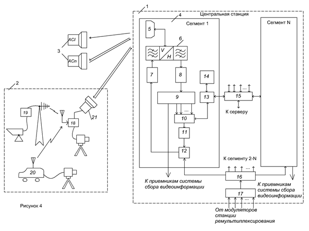
Fig.4 System UWMS-R block diagram
The modem is connected by input-output 10 to the switchboard 13 which is connected by one of inputs-outputs to the monitoring and management block 14, by other input-output is connected to one of inputs-outputs of a digital platform 15, and by an output is connected to an input of the upconverter 11. The upconverter is connected by output 11 to one of combiner inputs 12 that is connected by other input to one of power divider outputs N 16, and by an output is connected to the upconverter 7 which is connected by an output to diplexer input 6. The digital platform by N inputs-outputs 15 is connected to switches 12 of N CS segments 4, and by an output is connected to the main CS computer (server) which has connection to external distributive networks. The N multichannel power divider by it outputs 16 is connected to combiners 12 of N segments 4, and by an input is connected to the multichannel combiner 17 which by N outputs is connected inputs with N inputs of remultiplexing station modulators.
The video information gathering system 2 includes a post of a video information gathering 18 which is connected through radio - or the cable communication line with transmitting stationary points 19 or only on radio lines with mobile points of a video information gathering 20, and on a radio channel is connected with CS 1 by means of the transmit-receive block 21.
All data transmission network operating mode organization is assigned to CS modems 10 which quantity is equal to quantity of segments 4. Traffic of separate modems 10 unite CS digital platform 14, and the incorporated traffic arrives on the computer (the main computer of system – the server) which provides interaction with external networks of data transmission.
The scheme of the UWMS-R Central station differs from the system scheme – prototype UWMS those two new elements are entered into its structure – the switchboard 13 and the block of monitoring and management 14. The switchboard 13 is intended for allocation from the general data flow of that data which concern an auxiliary network of data transmission of a control path in gain factors of type USn user’s stations receiving and transmitting parts microwave transmit/receive head and video information gathering posts transmit-receive blocks and quality assurance of broadcasting signals accepted by them. In the monitoring and management block all functions of management and control that allows the operator to supervise a current condition of a network are concentrated. Management in gain factors of receiving and transmitting converters of user's transmit/receive heads and transmit/receive blocks of a video information gathering posts is carried out in an automatic mode by means of the special program containing in the CS block of monitoring and management.
User's station USn
User's station USn (Fig 5) consists of the antenna 1, the microwave transmit/receive head 2, the transceiver 3, tuner DVB 4 and the user's modem (CPE) 5. On the microwave transmit/receive head input is established the polarization selector 6 which on an input-output is connected to the transmit/receive antenna 1, by one of outputs is connected to the filter 7 which is connected by the output to an input of the low noise amplifier 8 which on an output is connected to one more filter 9 which on an exit is connected to an input of the amalgamator 10. The amalgamator is connected by other input to one of exits a heterodyne 11, and by an exit is connected to an input of the amplifier with gain control 12. From an exit of the gain control amplifier the signal on a coaxial cable arrives on the transceiver 3. On other cable from the transceiver 3 signal arrives on an input of the microwave transmit/receive head transmitting parts commutator 13 (Switch), and by other commutator input is connected to one more output of a local oscillator 11. The commutator output 13 is connected to an input of the filter 14 which is connected by the output to an input of the amplifier with gain control 15 on which input and on an input of the gain control amplifier 12 from the transceiver the signal of management in gain factor is given. The output of the gain control amplifier 15 is connected to an input of the power amplifier 16 which is connected by the output to an input of the polarization selector 6.
The signal from a reception part of the transmit/receive head arrives on transceiver 3 diplexer 17. One of diplexer outputs is connected to an input of the downconverter 18 which is connected by the output to an input of the multiplexer 19. The multiplexer 19 is connected by input-output to an input-output of the user's modem 5, and by an output is connected to an input of the upconverter 20 which is connected by the output to a microwave transmit/receive head 2 transmitting part. The user's modem is connected by 5 other input-output to an input-output of the commutator (switchboard) 21 which is connected by the second input-output to an input -output of the coder/decoder 22 which is connected by an output to control inputs of amplifiers with gain control 12 and 15 of microwave transmit/receive head 2. The second diplexer 17 output is connected to directed coupler 23 input which is connected by the output to an input of the detector 24, and the detector 24 is connected by output to an input of the coder/decoder 22.
Directed coupler 23 by it output is connected to an input of the tuner 4 from which the signal moves on the television receiver. The commutator (switchboard) 21 has an input of peripheral user's devices port with which help it is connected to the user’s computer or to a data transmission network.
Defining elements for user's station ASn are:
the switchboard 21, the coder/decoder 22, the detector 24 and the directed coupler 23. In directed coupler 23 broadcasting part of the signal received and converted to an intermediate frequency signal in microwave transmit/receive head, branches off in the passing power detector 24. The signal from the detector arrives in the modem 22 in which it is digitized. The modem forms the data for transfer on a network of management and monitoring for their inclusion in a return data link through the user's modem 5, and also accepts and will decode the data received from the user's modem 5 on direct data link. On the basis of the management commands received from CS on a direct data link the management signal intended for adjustment gain factor of microwave transmit/receive head 2 amplifiers with gain control 12 and 15 is formed.
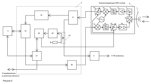
Fig. 5 User's station USn block diagram.
The transmit/receive block of a video information gathering system
The transmit/receive block of a video information gathering system (Fig. 6) consists of following elements: antennas 1, the microwave transmit/receive head 2, the transceiver 3, and the user's modem (CPE) 5. The microwave transmit/receive head 2 has no differences from applied as a part of user's station USn. The transceiver 3 has following differences (elements of similar appointment are numbered equally) concerning the same block of user's station USn:
- It is excluded directed coupler 23;
- The commutator (switchboard) 21 is excluded;
- The tuner 4 is excluded;
- The combiner 25 is added.
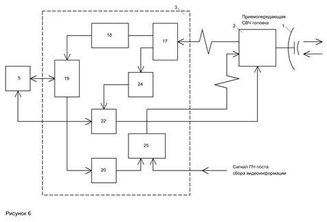
Fig.6 A video information gathering system transmit/receive part.
The tuner 4 use as a part of the video information gathering post equipment there is no necessity. Also there is no necessity in directed coupler 23 as all broadcasting signal goes to the detector 24. As there is no necessity for connection of the peripheral equipment of the user, there is no switchboard 21. The user's modem 5 is used only for reception management, and control signalling. After reduction of all signals arriving on a video information gathering post from the video information gathering points, to one kind, their coding, multiplexing of the received transport streams in a uniform transport stream and modulations by this stream carrier on intermediate frequency the modulated signal moves on the combiner 25. In it unites with a return information channel and the microwave head with which help it is transferred on CS moves on transferring part microwave transmit/receive head.
Application instead transmitter of the video information gathering channel the transmit/receive block allows to carry out adjustment from the Central Station on a direct data link of transmit/receive transmitting part gain factor and level of its output power that allows to reduce at reception of signals from several video information gathering posts levels difference on an input of CS receiving converter. In this case also antennas, at least, two types are used.
User's station US1
In UWMS-R application of user's stations US1 which have no return data link is supposed and consequently aren't subject to control and management from CS. The loop of automatic gain control (AGC) is applied to maintenance of a necessary dynamic range on an input of this type user's stations in their receiving converters which supplements AGC of receiver DVB-S.
Also antennas of two types with different gain factors are applied.
The UWMS-R operation description
In following sections the work description of UWMS-R is given.
Formation of a television broadcasting signals: Signals of TV broadcasting are formed by remultiplexing station (in drawing it isn't represented). The remultiplexing station usually represents a teleport which receives signals of satellite, cable, wireless TV, and also signals from local studio. On CS these signals are properly processed. This processing includes decoding of those signals which are coded by systems of conditional access of satellite and cable TV operators (descrambling), transport streams remultiplexing for the purpose of new multiplexes of TV programs formation and scrambling these streams by own system of address coding. After the specified operations necessary for scrambling DVB-S streams formation the received data flows are sent on modulators on which outputs are generated carrier modulated by multiprogramme TV signals.
The modulated carriers unite in a multifrequency group signal by CS multichannel combiner 17. Further the group signal divides on power on N parts (by quantity of system segments) by means of a power divider 16. On outputs of a power divider 16 it is received N copies of a group signal, each of which goes on the combiner 12 one of CS segments 4. After summation with a signal of a direct data link this signal will be converted and amplified by the upconverter 7, then arrives on an diplexer input 6 and, having passed it, is radiated by the sector antenna 5 in the form of a beam in width 360grad/N (where N – quantity of sectors of antenna system).
Formation of a direct data link (downstream): The downstream is formed by a transmitting part of the CS modem 10 (WMTS). In it DVB data packages with time division (method TDM) modulate preliminary established carrier and forming a direct data link. Further this signal will be converted to a necessary frequencies range, amplifies and summarized by means of the combiner 12 with broadcasting signals forming a full group signal of the direct channel. Further it will be converted and amplified by the upconverter 7 and, having passed through diplexer 6, is radiated by the sector antenna 5 in the form of a beam in width 360grad/N (where N – quantity of antenna system sectors).
The signals are received by user's stations USn 3 and by transmit/receive blocks of a video information gathering system posts.
Transfer of upstreams: Upstream signals are transmitted by stations of type АСn and transmit/receive blocks of a video information gathering system posts in a direction of CS sector antenna. Methods of frequency and time multiplexing (method FDMA/TDMA) are thus used. At use of this method of multiplexing quantity АСn that works on one frequency and transfers messages in the form of packages at the command of the CS modem 10. These commands are built in structure of the uplink channel of the data in the form of the special channel (control path). Such way reaches frictionless work of type АСn stations, and also monitoring and management of a video information gathering system posts transmitter work by transfer of upstream data packages and signals of system of gathering of a video information gathering system by them. By such principle the work of similar АСn stations which work on other frequency, and also those from them which belong to CS segments 4 with numbers 2 … N are realized.
Signalling by a video information gathering system: A video information gathering system has two-level structure. Necessity of such construction is caused by that the signals transferred by stationary 19 or mobile 20 video information gathering points can correspond to different standards, for example, DBS – for analogy points and DVB-Т – for digital. Besides, for signals of the first level it is difficult to receive sufficient range by transfer which would allow to transmit directly a signal on CS because a video information gathering points transmitters limited power (especially mobile), a low placement of transmitting antennas, and also difficult radio-waves propagation conditions (absence of "direct visibility», presence of a great reflected signals number and etc.). Inclusion in system structure of a video information gathering posts some quantity which placed so that for them the mode of "direct visibility» with CS was provided allows to solve this problem. The receivers 18 which are a part of the video information gathering posts transmit/receive block 21 (Fig. 4) receive and process the various signals arriving from a video information gathering points, and will convert them to a uniform kind (to a kind of DVB transport streams - TS). Further these TSs are multiplexing in the uniform datastream which modulates carrier on intermediate frequency. Then this signal arrives on the transceiver and microwave transmit/receive head of the transmit/receive block 21 in which it will be upconverted on frequency and amplifies for the further transfer on a radio channel in CS direction.
On each CS segment 4 signals from UСn and video information gathering posts 18 which are located in sector of the CS antenna 5 arrive. Having passed diplexer 6 the signals received by the antenna arrive on the low noise downconverter 8 in which they amplify and will be converted to signals of intermediate frequency. Signals of intermediate frequency arrive on a multichannel power divider of the converter 9. This divider has outputs quantity which is equal to quantity of CS modem 10 inputs plus one more output from which one of the received signal copies goes on a video information gathering system receivers (in Fig. 4 aren't represented). As these receivers usual tuners DVB can be used.
A control system of a network information part.
The control system of a data transmission network (NMS) is concentrated in DOCSIS WMTS. It supervises serviceability and the UWMS-R information part parameters by means of monitoring and management systems. Functions NMS include network operating modes control, administration, network service, and user charge levy from network users.
The sizes of a service zone usually depend on system gain of the radio-frequency equipment and transmitting and receiving antennas, meteorological characteristics of region in which system UWMS-R is located, and also the real relation a signal/noise reached in system. In general the radius of a service zone should be more 10Kм.
Though spectrum UWMS is wide enough in comparison with the frequencies bands defined for radio lines of type a point-point (PTP) and a point-multipoint (PTM) on lower frequencies, in system, except time and frequency, is applied as well spatial division of the signals arriving from user's stations, to increase in their quantity and network information capacity.
The increase in number of sectors increases CS cost as transceivers should repeat for each of sectors. However advantage of sector construction is that application of antennas with higher degree of a directivity which occurs at replacement of the omnidirectional antenna on sector antennas system reduces possibility of the effects coupled with a multibeam propagation mode occurrence, and thereof, reduces an intersymbol interference (ISI).
But decided advantages of sector antenna system construction is substantial growth of a data transmission network subscribers quantity and a video information gathering posts quantity at the expense of spatial division and possibility of a frequencies reuse.
The downstream (the direct channel): The access scheme for the direct channel - TDM with frame length from 3 ms to 6 ms. The channel pass-band is set in limits from 8 MHz to 20 MHz.
A transport stream frames contain time slots set which can be divided on starting slots and slots of direct access. To simplify data-handling procedure in CPE, it is necessary that the relative quantity not accepted slots in a frame are no more than 7 %. At transfer data rate in a downstream direction 41Mbps it corresponds to 50 ATM cells or 14 packages of MPEG2-TS in a frame in 6 ms. Everyone CPE can then to receive approximately to 3.5 Mbps.
The central station is capable to transfer of several channels simultaneously. However CPE can accept only one channel. It can be switched to various frequencies, but such switching can demand a time interval having duration that equal to several time slots.
The frame structure will be coordinated with MPEG-2 Transport Stream. The MPEG2-TS MUX package contains 188 byte into which enter one byte of the synchronization, three bytes of heading containing the service information, the information about scrambling and management, and the subsequent 184 bytes MPEG-2 or the additional data. Packages scrambled with use of pseudorandom binary sequence (PRBS) with the period of 1503 bytes that corresponds to 8 packages. Synchronization bytes are not scrambled. The first byte of synchronization is supplemented.
According to specification DOCSIS channel coding assumes 5 components: scrambling, interleaving, Reed-Solomon block coding, convolution encoding and, at last, constellation formation (mapper).
The direct channel uses the norms defined by standards DVB for satellite services in ranges of 11 GHz and 12 GHz. The system is optimized for an access method on one TDM carrier, but allows to apply and the multifrequency access (FDM) scheme. As typical data rate the multiple by 8 Kbps rate is defined. The frame structure is equivalent to specification DAVIC and contains 188 byte.
The upstream (the return channel): The access scheme in the return channel is TDMA. A frame length is the same as for the direct channel, i.e. between 3 ms and 6 ms. CPE regulate a choice of a package transfer time moment in an return direction before coincidence to slot borders in a frame of an upstream on CS at the set admission on time. Its accuracy is defined by a difference in a propagation delay that is corresponded to radius of a service zone. The control system of a network distributes set adjacent time slots so that to generate longer slots the network access that preventing collisions by transfer of TDMA package which can accompany access CPE to a network. Synchronization is reached thanks to that CPE adapts the transfer moment in reply to feedback by synchronization mistake until while this error doesn't become less duration of one symbol in an upstream (a guard interval in a package has the duration equal to 4 symbols). The central station makes periodic inquiries about a synchronization error for achievement of necessary accuracy.
The package of the upstream data contains 68 byte. The upstream frame contains F slots where F depends on transmission data rates in an upstream. F slots are divided on request slots, direct access slots, and reserve time slots. The slots quantity parity each type is dynamic.
Shorted Reed-Solomon RS (204,188) code is chosen as a block code which is defined for an uplink. At entrance BER nearby 7*10-4 or less and at unlimited bytes interleaving the decoder should carry out QEF (quasi error free) an output at which BER makes from 10-10 to 10-11. Convolutional interleaver is just the same, as well as applied in a downstream under specification DAVIC (T=12, M=17), and also is the block coder. The block decoder should work at error rate on an input (BER) that equivalent to "the rigid decision”, between 10-4 and 10-2, and should provide BER nearby 2x10⁻⁴ or less.
The roll-off factor for the filter with the type characteristic «a root square of the raised cosine» is equal 0.35 that differs from specification DAVIC where it is applied either 0.2 or 0.35. At use of digital filter FIR it is possible to make alignment (equalization) non-linearity in the channel. This filter isn't standardized therefore its kind will depend on concrete channel parameters. The modulation scheme is usual Gray-coded QPSK.
WMTS allows to controlling the power given by user's modems, and at the expense of it carries out adaptive suppression of an ingression noise in the receiver in real time. Measurement and the analysis of the signal/noise rate in receiver WMTS is for this purpose made. On the basis of this analysis special commands for management of user's modems transmitting parts are developed. Further the signal which has arrived in receiver WMTS is processed in an equalizer that allows to increase throughput of cable modems DOCSIS at the expense of granting practically in all cases of possibility of their work in a mode 16QAM instead of QPSK. The equalizer corrects a signal at influence on it frequency fadings, peak distortions, and also non-uniformity of a group delay. If nevertheless noise can't be suppressed (for example, at very big level of ingression noise or a strong interference) WMTS can prevent consequences of noise influence at the expense of a modulation type change or transition in a frequency hope mode (mode CDMA).
For improvement of all modems DOCSIS parameters which work as a network part in WMTS it can be used the additional receiver that is included in parallel to four receivers which are intended only for a network subscriber’s service. This receiver gives to operators possibility of an operational administration in any of input ports parameters, without interfering thus with their work on servicing. For this purpose the additional receiver is connected to in parallel chosen receiver so the operator can measure the traffic and signal parameters in real time for any of functioning ports. Simultaneously, this receiver can have access to the network information and the full list of the cable modems working on any of receivers which is subject to monitoring. Thus, while any of receiver ports works at a total load, the additional receiver can increase access to other return channels by reception of tests for each of receiving channels and an estimation of their loading.
Auxiliary data transmission network for monitoring and management in gain factors of microwave transmit/receive heads up- and downconverters: The auxiliary data transmission network for monitoring and management in gain factors of active microwave transmit/receive heads up- and downconverters can be constructed as a usual IP-network which uses a wireless network of system UWMS-R data transmission as transfer media. On UWMS-R return information channels (upstream) the data intended for broadcasting signal level monitoring that received by user's stations is transferred. This data is entered into the return channel by means of the commutator (switchboard) 21 (Fig. 5). At the Central station the monitoring data arriving from all active user's stations on a modem WMTS 10 output (Drawing 4 see) separates from the given clients and goes to the block of monitoring and management 14. Here on the basis of the received data on certain algorithm management commands for each of user's stations which by means of the switchboard 13 are entered already into a direct data link are developed and transferred on a radio channel simultaneously to all user's stations which are in given sector. To reduce quantity of the information intended for transfer on the direct channel it is necessary to hand over only the information on microwave heads converters gain factor change. On an each of user's modems (CPE) 5 output all these signals are present and arrive on the switchboard 21 (Fig 5) with which help the data concerning only to a control system separates. In the coder/decoder 22 the management commands concerning given user's station will be decoded, and given user’s station USn microwave transmit/receive head up- and downconverters or video information gathering posts transmit/receive blocks control signal is developed.
Existing techniques level
System UWMS which represents interactive system MVDDS (multimedia system) combined with
a video information gathering system (video surveillance) which has two-level structure is known.
By means of the given system following functions are realized:
- Signalling of multiprogramme TV broadcasting;
- An exchange in an interactive mode the internet data and its appendices with User's station set at use of own wireless return channel;
- An exchange in an interactive mode the internet data with corporate users on the allocated channels;
- Transfer on return channels, except the data, on the own frequency channels and in real time mode the multiplexes consisting of several transport streams which are formed by a video information gathering posts (top level of a video information gathering subsystems);
- TV signals transfer on wire and wireless transfer channels from a video information gathering points set (stationary or mobile points of cameras placement) on a video information gathering post (the bottom level of a video information gathering subsystems).
Prototype lacks:
1. The basic UWMS system lack is rather low level of user's stations receivers and the receivers established in each of Central (Base) station sectors adaptation to the big range change of received by them television broadcasting signals and the signals transferred by a video information gathering system levels. This levels range is a consequence of distances from the Central station to the subscriber and a video information gathering posts locations wide spacing and also attenuation in a rain. The big levels change on receivers inputs in system UWMS can be partially compensated for account receivers DVB-S AGC and at the expense of antennas with various gain factors application that can appear sufficient in usual conditions. But in the conditions of intensive loss the deposits losses from which can't be neglected for signals with the frequencies used by system UWMS the specified methods of received signals levels change (a dynamic range on a receivers input sizes) indemnification are obviously insufficient.
2. The second of essential lacks are great difficulties and expenses of time for system installation as each of user's stations and each of the video information gathering posts transmitters demands individual antennas adjustment not only on a corner of a place and an azimuth at orientation to the Central station but also individual selection of antennas gain factors (diameters of reflectors).
3. System operation as at the Central station the information only about work of an information system part is accessible to the operator is complicated, and operator is not known about quality of television signals reception. At the same time, monitoring of television channels transfer is especially important as in system work TV broadcasting signals which should be transferred with bit errors rate no more BER = 10-8 should be priority. Such high BER the mode of real time demands by transfer both broadcasting signals and the signals transferred by a video information gathering system.
At the expense of what in the UWMS-R system these lacks are eliminated.
System UWMS-R differs that for the purpose of indemnification increased at the expense of losses in a rain a dynamic range on receiver’s inputs, except those measures which have been applied in system UWMS, following changes are made to it:
- Into scheme system CS (Fig. 4) are entered the switchboard 13 and the block of monitoring and management 14.
- Into the schemes of User’s stations USn microwave transmit/receive head 2 and a video information gathering post transmit/receive block variable gain amplifiers 10 and15 (Fig. 5) are entered.
- Into the scheme of User's stations USn transceiver 3 (Fig 5) the directed coupler 23 and the passing power detector 24 are entered.
- Into the scheme of User's stations USn transceiver 3 (Fig. 5) the switchboard 21 and the modem 22 are entered.
- Into the scheme of a video information gathering post transmit/receive block transceiver (Fig. 6) the detector of falling power 24 and the coder / decoder 22 are entered.
- Into the scheme of a video information gathering post transmit/receive block transceiver the combiner 25 is entered.
At the expense of the measures concerning points 2, 3 and 4 the increase in a dynamic range on the User's stations of type USn receivers inputs is reached.
At the expense of the measures concerning points 2, 5 and 6 levels difference of signals which are radiated by transmitters of a video information gathering posts transmit/receive blocks transmitters reduction and, thus, reduction of a demanded dynamic range of the Central Station sectors 1-N receivers is reached.
Functioning of all system is provided with measures on point 1.
It is necessary to notice that in spite of the fact that regulation in system is carried out on the basis of powers measurement in broadcasting channels this regulation is very useful and by direct and return channels transfer of own data transmission wireless network as promotes reduction of a adjustment range in the user's modem (CPE) that is especially important at work in mode TDMA.
The improvements brought in system UWMS-R allow it to keep working power in presence of intensive deposits but they are useful and in usual conditions as help to lower expenses for installation of system and to lower working costs.
CONCLUSIONS
Thus, the decision of the put technical problem probably only on the basis of the technical decision offered for system UWMS-R which will allow to use a system working in Ku band in regions with the big deposits intensity. However technical decisions used in declared system can give positive economic benefit and at system use in usual environmental conditions at the expense of decrease in expenses of time for installation and working costs. The given decision also can be useful in regions with slightly smaller deposits intensity but at system work in higher frequencies ranges.
Authors

Petro Himich
Engineer. Team Leader for Company "ROKS"