Wireless video surveillance
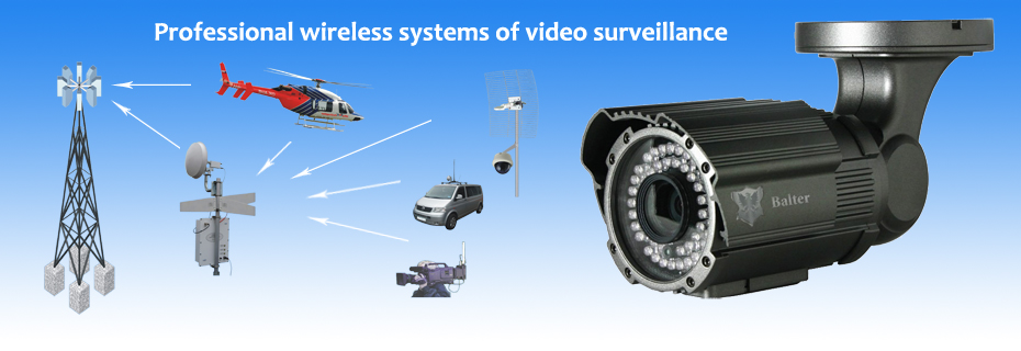
Video Surveillance Systems
PJSC “ROKS” develops, manufactures, and installs the municipal level professional systems of video surveillance. Our systems of video surveillance have two levels: top (in Ku-band) and bottom (in S-band). At the bottom system level the video information gathering arriving from cameras of stationary and mobile video surveillance points on so-called video surveillance post is made. At top level signals which collect in video surveillance posts are transmitted in the Central station direction. Such technical decision allows to realizing such throughput of system which surpasses throughputs existing and perspective WLAN and is comparable only with throughput of FOLs.The Problems of existing video surveillance systems
The problem consists that all extended to today LANs including advanced of them – WiMAX, possess insufficient throughput for distributed video surveillance networks that created on their basis. Besides, all of them (both Wi-Fi, and WiMAX, and perspective LTE) have a slope of the traffic towards the direct (downstream) channel while a video surveillance networks demand, on the contrary, a slope of the traffic towards the return (upstream) channel on which the basic volume of a video information is transmitted while on the direct channel only management signals are transferred.
Conclusion. Construction of a professional wireless video information gathering (video surveillance) network on the basis of extended, and also perspective and specialized local networks isn't expedient.

Professional wireless video surveillance network architecture
At a professional network design we suggest to refuse:
1) from a time duplex, having replaced its frequency duplex;
2) from TDMA mode in the return channel. All transfer time should be given transfer of one radio channel to a continuous mode. The increase of transferred television signals quantity is reached not at the expense of time division, and at the expense of digital multiplexing.
Certainly, such mode will demand use of the big frequencies band. Big enough band can't be realized in those frequency ranges which are used traditional LAN, i.e. ranges L and S, and even C. We have stopped the choice on range Ku (more particularly, on a band 10.7 – 11.7 GHz), in which allocation enough wide frequencies bands are probably.
The main key features of a network offered by us:
Our network is two-level. It consists of top level which represents the fixed data transmission network consisting of the Central Station, constructed around system of sector antennas (having from 4 to 8 sectors), and sets so-called “Posts of a video information gathering (video surveillance)” which represent transmitters of the digital multiplexes including from 8 to 16 television programs of usual quality (SD). The main variant of network architecture assumes a configuration of type "star" in which video information gathering posts being in limits of the given Central Station sector immediately connect to her. Such architecture is most rational, as with its help the greatest throughput of a network is reached. However to realize it in the conditions of a big city without resorting to additional capital construction it is not always possible because of high-rise buildings which can get in way of the beams bridging a video information gathering post from Central Station sector antenna. In quality of a "spare" variant it is possible to apply "a treelike" configuration. In this case the network is designed in the form of a hub chain to which the branches bridging these hubs with posts approach. The Central Station is on the chain extremity. Such chains can be a little. A problem both "star" and "tree" is achievement of mode «line-of-sight» (LOS) for all transmitters and receivers in a network.
For unequivocal separation of posts on sectors the division of all available frequencies band into two parts (if all frequencies band makes 1 GHz half will be peer 500 MHz) is required. We are guided by standard DVB-S/S2 which assumes that a frequencies grid step of radio channels is equal of 35 MHz. Then in the designated frequencies band it is possible to place about 14 posts of a video information gathering. Through one sector the channels frequencies are repeat. At use of standard DVB-S2 the programs quantity of usual quality will be peer to 224th. Тhat is in one sector the signals transferred by 224 cameras can be collected. In the presence of 8 sectors the cameras total quality in network will be peer to 1792! The Total amount of the information transferred in a network reaches 7.168 Gbps!
The bottom level is made by the small networks including to 16 so-called «Points of the video surveillance». The point of a video surveillance is an aggregation of the camera, the video signal transmitter and the remote control signal receiver. Points of a video surveillance can be stationary and mobile. As each of them transmits a signal only from one camera, radio channels can take place in ranges L and S. Stationary points by means of the referred antennas contact posts of a video surveillance mainly in LOS mode. They suppose signals of the most different standards use including analog that allows to use at this level inherited (i.e. used earlier) elements of the bottom level network. Mobile points of a video surveillance are mainly systems of automobile basing. Thus the PTZ video camera, the output power amplifier of the transmitter and the antennas settle down on a car roof, and all other equipment – in its salon. Remote control of the camera can be carried out for choice or the operator at the Central Station, or the operator who is in salon of the car.
Other variant of mobile station is mobile reporting television station. In interests of public order protection and tracking safety of traffic organs the mobile point of a video surveillance can be placed by the helicopter (piloted or pilotless). In all cases of mobile application the transmitting standard DVB-T which allows to conducting transfers from a vehicle during movement is used. Besides, mobile points can work in NLOS mode (non light-off-site).
View of a video surveillance post which has the container with a thermostat. (One reception antenna UHF is conditionally shown only)
Reconciliation and reduction to a common denominator of the signals arriving from points of the video information gathering and corresponding to different standards is a problem of a video surveillance post. A post ultimate goal is transfer of a multiplex from 8-16 ТV signals according to standard DVB-S/S2 (types of modulation QPSK/8-PSK). At first signals of each of points are received separately everyone by the receiver. Analogue signals are digitized and compressed. Further transport streams DVB are formed of them. Digital signals also are processed to level of transport streams DVB. Further these transport streams are multiplexing, and the multiplex of television signals is formed of them. Then according to standard DVB-S/S2 modulation of carrier on intermediate frequency is carried out. The equipment with which help all this processing of signals is carried out takes place in a small heated premise or in the special water-proof container supplied with a thermostat. Only the transmitter (the powerful upconverter-BUC) and transmitting Ku–band antenna, and also the antennas receiving signals from points of the video surveillance are placed outside of premise or container.
Such architecture provides the maximum flexibility, multi-variant approach and that the most important thing, scalability of a network.
The block–diagram of Video Surveillance Post. System of cameras control
The placement of control system equipment for automated TV cameras (on an example only one camera)
The transmitters of a video information gathering points and PTZ video cameras parameters control made remote. The remote control of transmitter is carried out by means of remote control receiver into which structure enter LNA, the remodulator, the decoder and the decoder of control commands, and key parameters of options are reflected by the indicator located on the forward panel.
The majority of video cameras which are supposed to be used within the limits of the given system are automated. They can be remote directed to surveillance object on two coordinates and have zoom lenses. The remote control transmitter carries out frequency modulation of carrier by low-speed (up to 19.2 Kbps) digital signal. At the output power of the transmitter peer 1W and use pin omni-directional antennas necessary range of a signal transmission from the central station to surveillance point even is provided at NLOS mode. In a figure one camera is conditionally shown only. From one control panel it is possible to control operation more than 200 cameras.
The chairman of the PrJSC “ROKS” board Ksenzenko P. Y.
Authors

P. Y. Ksionzenko
CEO of ROKS