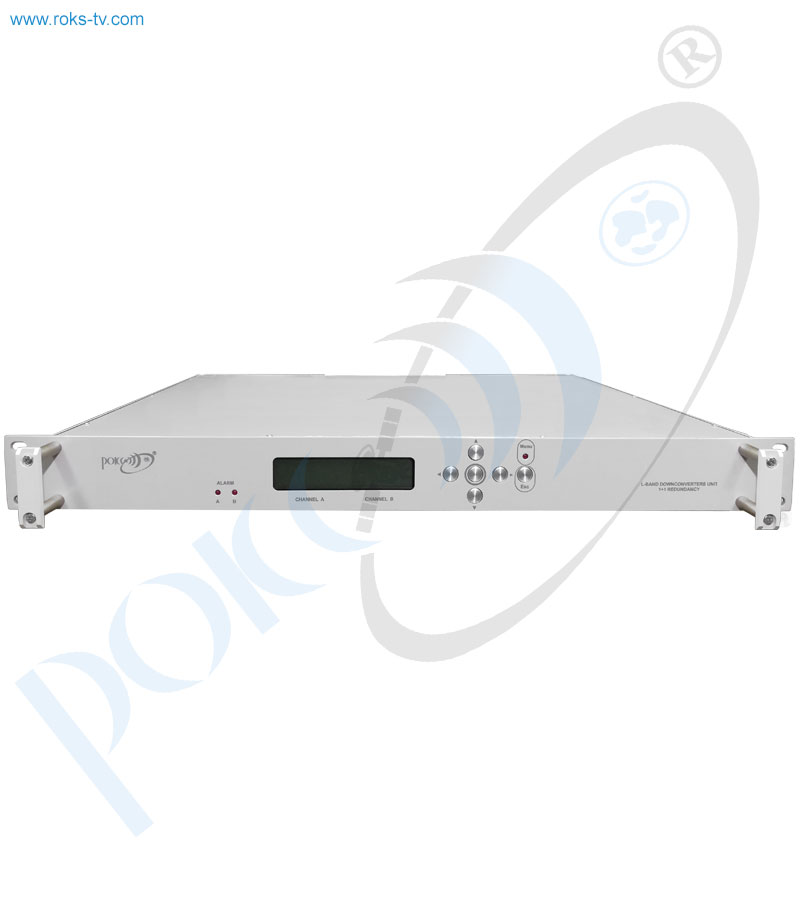
L/70MHz Downconverters unit with 1+1 redundancy
- Description
- Parameters
- Downloads
The downconverters unit with 1 + 1 redundancy is a basic chassis on which are located: controller board, indicator, redundancy board, RF power divider and IF signal switch. The downconverters unit with 1 + 1 redundancy also includes two replacement blocks - Block A and Block B.
To ensure a high degree of reliability (readiness of the Downconverter unit) automatic hot redundancy of the converter blocks and power supplies is provided according to the 1 + 1 scheme.
The design of the Downconverter unit assumes automatic switching to the standby unit when one of the units fails and allows quick failed block replacement without users interruption of maintenance for the spare that is included in the delivery set.
KEY FEATURES:
- The signal in the receiver passes through three stages of filtration.
- To ensure a high degree of reliability (readiness of the downconverter unit) automatic hot redundancy of converter units and power supply units is provided according to the 1 + 1 scheme.
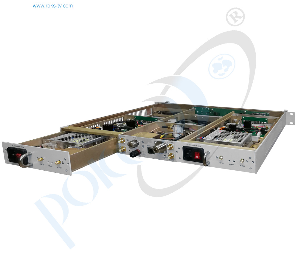
- Replacement blocks are frequency converters with double conversion L / 2400 MHz / 70 MHz.
- The replacement blocks, except the frequency converter modules, also include the network switching power supplies (AC/DC converters) and detector modules.
- The detectors module of the replaceable block has LED indicators (on the back panel) of the input RF signal and the output IF signal levels.
- The parameters of downconverter unit can be controlled by buttons on the front panel. Set parameters can be controlled by LCD.
- The downconverters unit with 1 + 1 redundancy can be mounted in standard 19" rack. It has a vertical size of 1U.
MAIN FUNCTIONS:
- Frequencies converting into L-band when operating in the satellite communication and television L, S, C, X and Ku-bands systems to the standard 70 MHz IF signal for further processing on this IF.
- Automatically turns on the backup unit when one of the units fails and allows a quick replacement without users interrupting the maintenance of the failed block to the spare.
- The circuit that generates the ALARM signal analyzes four input signals: the RF level, the IF level, and the two loop lock signals of the first and second conversion stages.
- ALARM signals are generated in the detector modules which are fed to the backup board on the base chassis to decide which of the replacement blocks is currently active.
- To adjust the gain factor of the downconverter module, a variable step attenuator is used in the radio frequency path with a control depth of 30 dB. Adjustment of attenuation introduced by the attenuator is made by either keys on the front panel or remotely.
| Parameter name, units | Nominal value, tolerance |
|---|---|
| Input frequency range, MHz | from 950 tо 2150 |
| Frequency tuning step, kHz | 1 |
| Frequency instability, ppm | 0.01 |
|
The spectral density of phase noise power, dBc/Hz, when detuned from the carrier by: 100 Hz 1 kHz 10 kHz 100 kHz 1 MHz |
-70 -90 -95 -95 -100 |
| Channel bandwidth, MHz | 36 |
| The maximum allowable input signal level, dBm | - 20 |
| Output power level with 1dB compression (P1dB out), dBm, not less than | 0 |
| The IMD3 value with two output signals of -13dBm, dBm, not more than | - 40 |
| Conversion gain, dB, not less than | 40 |
| Gain adjustment depth, dB, not less than | - 30 |
| Gain adjustment step, dB | 1.0 |
| Input impedance, Ohm | 50 |
| Input return losses, dB | - 18 |
| Control and monitoring mode | Local and remote |
| Remote mode interface | Ethernet 10/100 Base T |
| Impedance of radio frequency output, Ohm | 50 |
| VSWR radio frequency output | 1.8:1 |
| Spurious emissions in the working band, dB, not more than | - 60 |
| Reference oscillator frequency, MHz | 10 |
|
Phase noise of the reference oscillator, dBc/Hz 10 Hz 100 Hz 1 kHz 10 kHz |
-125 -140 -150 -155 |
| AC power supply voltage from AC mains with frequency 50Hz, V | 100 – 262 |
| Power consumption in hot standby mode 1+1, W, not more than | 45 |
| Overall dimensions (without connectors), mm | 482 х 400 х 44 |
| Weight, kg, not more than | 7.0 |
Taking into consideration that we (ROKS PrJSC) are developer and system integrator, also do not stop on our technical growth and improvement, know that view of all our devices and equipment including their technical parameters may be different from pictures presented on website and parameters listed on each device webpage.
Note! All details customer has to confirm in advance during ordering and before payment. Those parameters that were not specified and / or were not agreed while ordering will be implemented as basic at the discretion of the manufacturer. Each our customer has 1.5 year warranty and 7 year aftersales support for whole range of our products.