UWMS-R as Advanced UWMS That Assigns For Working in Heavy Rain Regions
Ukrainian Patent № 54643, 25.11.2010
P. Ksenzenko, M. Boichenko, P. Himich,
“ROKS”-company
The invention concerns to a radio engineering, in particular to systems which provide television broadcasting, gathering of a video information, and data transmission within a certain geographical zone on district.
The device which represents the wireless system which is a network of cellular communication is known and uses set of channels with distribution on frequency according to a method of frequency division multiplexing (FDM). For wireless communication realization between the user’s equipment (UE) and base station (NodeB) define, at least, one parameter which depends on a frequencies band, for, at least, one set of channels FDM at the expense of processing in NodeB. Depending on a frequencies band parameters transfer from station NodeB serving a cell to station NodeB serving other cell. Depending on a frequencies band the parameter can be defined on the basis of the response to the scheduler information and/or on the basis of concerning to frequencies band measurements which are made in NodeB. The specified system has the first configuration receivers on the power, the second configuration on power and receivers of the scheduler messages which specify in a frequencies band FDM.
Frequencies band choose from the list which consists, at least, of the first and second frequencies band FDM. Terminal UE transmits a signal of the first power level in case the scheduler message will specify in first band FDM, or the second power level if will specify in any other band [1].
Lack of the presented device is that at simultaneous reception of broadcasting and information signals compensation of losses in a rain at the expense of increase in Central (Base) station CS (BS) transmitter power does not allow to reduce a dynamic range of user's receivers to necessary level. At the expense of transmitter CS output power change it is possible to support only at constant level equivalent isotropic radiated power (EIRP) on a service zone border. If for compensation of losses in rain CS will start to increase power on an output of its transmitter, the signal level received by close located stations for which in a rain it is much less than loss, than for being on a service zone border, will increase practically by the same size, that is the dynamic range of receivers remains invariable.
Effective from the view point of a necessary dynamic range achievement on receivers CS and User's stations (US) inputs the way of transmitters output power change according to which it adapts for each of receivers individually on the basis of a method “from a frame to a frame”, cannot be applied as the basic adjustment mechanism by simultaneous transfer of broadcasting and information signals. The increase in reply to increase in losses in a rain of CS transmitter output power allows to support at constant level EIRP on a service zone border, but does not allow to reduce a dynamic range required for user's receivers on an input as at such increase approximately on the same size power on the receivers inputs located near to CS the US for which losses in a rain are small increase also.
Closest of the devices applied on the same appointment, as declared, UWMS which includes CS, gathering of a video information subsystem and set the US is. CS it is divided into the segments which quantity is equal to quantity of antenna system sectors. CS has communication with such external systems: station of remultiplexing, forming television broadcast signals, external in relation to CS data transmission networks and system of receivers and means of video information record and display. The subsystem of a video information gathering has two-level structure and consists of video information gathering posts and set of video information gathering points (points in which video cameras are established).
Use the USs of two types: the first type – what are intended for reception of broadcasting signals and direct data links signals, and also for data transmission to CS under the return data link, and the second type – what are intended only for broadcasting signals reception. By means of the given system such functions as can be realized:
- A multi-program television broadcasting signaling,
- An exchange in an interactive mode the Internet and its applications data with user's stations set at use of own return channel,
- Data exchange with corporate users on allocated channels,
- Transfer on return channels, except the data, on the frequency channels and in a real time mode, multiplexes which consist of the several transport streams formed by video information gathering posts (top level of a video information gathering subsystem),
- Transfers on wire and wireless channels of television signals from several video information gathering points (stationary or mobile points of an arrangement of video cameras) on a video information gathering post (low level of a video information gathering subsystem) [2].
The specified system is chosen as a prototype.
Lack of the presented device is that rather low level of US receivers and the receivers established in each of CS sectors adaptation to the big change range of television broadcasting signals levels received by them and the signals transferred by a video information gathering subsystem is peculiar to system UWMS. Such big change of levels range is a consequence of the big distinction in distances from CS to the subscribers and video information gathering posts location, and also attenuation of signals in a rain. The big change of levels range on receivers inputs in system UWMS can be partially compensated for account AGC in DVB receivers and at the expense of antennas with various gain factors application that can appear sufficient in usual conditions. But in the conditions of heavy rains losses from which cannot be neglected for signals with the frequencies used by system UWMS, the specified ways of the received signals levels compensation (size of a dynamic range on receivers inputs) will be for certain insufficient. Other of essential lacks are great difficulties and expenses of time for system installation as each of the US and each of transmitters of video information gathering posts demands not only individual adjustment of antennas at orientation on CS on a elevation and an azimuth, but also individual selection of antennas gain factors (dish diameters). System operation as for the operator on CS there will be accessible only on information part of system work is complicating, and it will be known nothing about quality of television signals reception. At the same time, monitoring of TV transfer channels is especially important because in system work television broadcasting signals which should be transmitted with bit errors rate not big than BER = 10-8 should be priority. Such high BER the real time mode demands by transfer, both broadcasting signals, and the signals transferred by a video information gathering subsystem.
One of those reasons which obstruct with achievement of expected technical result at use of the known device, that in the heavy rains conditions the general dynamic range on USs receivers inputs, and also CS receivers at video information gathering subsystem signals receiving by them, will be too big is and cannot be provided by those means which are available in system UWMS. For acknowledgement of it we will result such calculations.
The first dynamic range component are losses in a rain. Losses of a signal at the expense of absorption in a rain substantially depend on frequency. On frequencies below 5 GHz these losses in most cases can be neglected. But on the fixed communication and broadcasting lines, working on frequencies above 20 GHz, losses in a rain become a primary factor limiting communication range. Naturally, losses in a rain depend on its intensity. In a heavy rains zone on the foreground there is a peak rain intensity which is observed throughout 0.1 % of time that corresponds to usual value of a line readiness 99.9 %. It is much more important, than the general annual norm of rains. Peak intensity strongly depends on a geographical zone. In droughty regions rain intensity can make only a few millimeters per hour. In regions with very heavy rains peak values of intensity can reach to 150 mm/hour. All calculations for communication systems can be conducted taking into account hourly average distribution of rain intensity for the worst month of year. The easing size at absorption of a radio signal by hydrometeors V in dB is defined under the formula:
V=-y*Rэф where y - attenuation factor, dB/Km, Rэф - effective length of a line, Km, along which the attenuation factor is approximately constant and equal .
The attenuation factor, for example, on frequency of 11 GHz for region with rain intensity 50 mm/hour is equal about 2 dB/Km. It means that the stock on attenuation on a line in length of 15 Km is equal in a rain approximately 30 дБ, application of broadcasting and data transmission systems which work on higher frequencies, than applied in declared system, in regions with such amount of precipitation in general is impossible.
Each of sectors CS transmitter output power level has the fixed size. This size is gets out maintenance of minimum necessary relation a signal/noise (SNR) calculation for the most remote subscriber station under the worst receive conditions. A component of a dynamic range is also signal attenuation in a rain which depends on distance between the USs and CS.
Declared system UWMS-R is a fixed communication system that is position in space of all subscriber stations rather CS is known in advance. We will admit that the CS service zone radius is equal 15 Km, and the most approach from closely spaced subscriber stations is from CS on distance of 150 m. Then the propagation lines lengths rate for the station which are on border of a service zone, and the station which are from CS on distance of only 150 m, will make 100:1.
The received signals powers relation for these stations, expressed in dB, is calculated under the formula which is recommended by the International Telecommunication Union (ITU) and looks like:
10N*log d = PT (dBm) + GT (dB) + GR (dB) – 32.44 – PR (dBm) – 20 log f (MHz). where: PT = output transmitter power (dBm);
GT = the transmitter antenna gain factor (dB);
GR = the receiver antenna gain factor (dB);
f = average working frequency of a radio channel (MHz).
Factor N named losses exponent and characterizing radio signal propagation conditions on a line, we will choose from Table 1.
| Propagation conditions | Losses exponent |
| Free space | 2 |
| City conditions | 2.7 - 3.5 |
| City with dense many-storey building | 3 - 5 |
| Building directly on a beam way | 4 - 6 |
Let's choose N = 2.7. If the relation of distances equally d1/d2 = 100, then 10N*log d1/d2 = 10* 2.7*log 100 = 54 дБ.
Thus, the signals dynamic range on USs receivers inputs who is caused by distinction in distances to CS, will be equal 54 dB (a mode almost to "line-of-sight”, but taking into account city propagation conditions). This component of a dynamic range is a constant and practically does not depend on time. If to consider losses in a rain which are a variable dynamic range component in power levels of received USs and CS signals on USs receivers and CS receivers of video information gathering subsystem inputs will reach possible difference 84 dB.
The method which most often use for increase in a dynamic range at a receiver input, is use of automatic gain control (AGC) in the receiver. As receivers in a broadcasting part the US and in a CS video information gathering subsystem apply standard tuners (set-top box) standard DVB. The signal admissible levels range on DBS tuner input at work in a land broadcasting systems makes from – 50 dBm to – 20 dBm that corresponds to AGC depth nearby 30 dB. Some reduction of control depth in AGC scheme rather 40 dB which correspond to broadcast satellite channels receiving, speaks higher own noise level of land broadcasting systems receivers concerning noise in DBS systems because of what the control range bottom level raises approximately on 10 dB, and the control range decreases to 30 dB. However it is obviously not enough this range for all range of receiver input signal level change full compensation which as it has already been told, can reach 84 dB. In declared system UWMS-R for partial compensation of such big received signals level difference which is peculiar both to US receivers, and to intakes which belong to CS video information gathering subsystem receivers, the way of corresponding choice gain factors (diameter of dishes) user's stations parabolic antennas and respective choice of gain factors US receive and transmit MW converters and receive-transmit MW heads transmitting parts converters of a video information gathering posts can be applied.
Such control is carried out in US receive-transmit MW heads and can be realized at the expense of additional AGC loop which covers high-frequency receivers stages. AGC voltage simultaneously can be used and for control on the same size of receive-transmit MW heads transmit parts gain factors that is possible thanks to receive and transmit channels similarity. Such way is simple enough, but has essential lacks. Receive-transmit MW heads receive part receives not only broadcast signals, but also and a direct information channel (downlink) signal. At gain factor adjustment the priority should be given television broadcasting signals as they demand transfer to a real time mode, and admissible at their reception error bit rate on two order more low, than necessary for information channel correct reception (10-8 against 10-6). If all control in broadcasting channels to concentrate on the US operatively to supervise reception quality by it of broadcasting signals, being on CS, it will be impossible. At the same time, one of the important MAC components in the central station (WMTS) modem is the quality management program (QoS) which allows to operating work of data transmission network flexibly. The similar system is necessary and for broadcasting channels.
One of the lacks inherent in gain adjustment systems which are completely concentrated inside the USs, the big complexity and duration of all system installation process is. It will be necessary to establish threshold values for AGC in each of receive-transmit MW heads individually taking into account a distance to CS that at a considerable quantity of subscribers a lot of time will demand. For lack of all system monitoring work on CS it is impossible to react operatively to receiving conditions degradation for separate US and to force with its work mode. Therefore gaining management in sizes of factors, both receivers, and transmitters it should be spent distantly and automatically from CS equipment room. At use AGC in the receiver (DVB tuner) and remote adjustment mode of receive-transmit MW heads receiving and transmitting parts the general levels difference compensation will make 64 дБ. To full compensation does not suffice still, at least, 20 дБ. The further compensation can be carried out at the expense a service zone division which is concentrated in sector with a beam corner 360 deg./N, at least, on two parts. The first of them is concentrated in approached to CS to a zone, where signal level high enough. Here it is possible to take advantage of the antennas having on 20 дБ smaller gain factor (smaller dish diameter). On the contrary, in a remote part of a zone we will take use of antennas with the maximum gain factor. Now we will obtain a necessary general dynamic range 84 dB.
Range of signals levels change received the US which mirrors a radiated by CS transmitter signal level dependence in US receivers inputs only from distance to CS at power level on CS transmitter output corresponding to power which is necessary for obtaining in the most remote user's receiver minimum SNR plus loss in a rain at the maximum removal from CS. Signal level dependence on losses in a rain which, being expressed in dB, are proportional to distance to CS, looks like a straight line if received power has a logarithmic scale. By transfer of television signals the direct broadcast channel and the return channel of the video information gathering system are similar, as in they use identical modulation type and the same frequencies band. For dynamic range reduction the signals received by downconverters and receivers (DVB tuners) should be changed to the same size, as their receive converters gain factors. That such system successfully worked, it is necessary to enter into it the feedback channel on a received US signal level. As the information transfer physical channel about a signal received the US level it is the most convenient to use the return data link (upstream) own information part of system, and for management in gain factors of receive-transmit MW heads US receive and transmit converters and video information gathering posts receive-transmit blocks – the direct data link (downstream). Essential changes to the block diagram as separate sector CS, and in video information gathering post scheme for this purpose was necessary to make.
The task in view dares because system UWMS-R includes the central station, a video information gathering system and user's stations, thus the central station has segments, each of which has the sector aerial which on an input-output is connected to an diplexer output which on an input is connected to the upconverter, and on an output – with the downconverter which is connected by the output to the downconverters block which N – outputs is connected to the modem (WMTS), and an output is connected to video information gathering system receivers, and the output connects to the main computer (server) which has an interface to external distributive networks, and an output the modem is connected to the upconverter input, which the output is connected to one of combiner inputs which other input is connected to one of N –channel power divider inputs, and an output is connected to the upconverter, which is connected by an output to diplexer input, the multichannel power divider by N –outputs is connected with N – segments combiners, and the input connects to the multichannel combiner which N – inputs is connected with N – modulators of remultiplexing station, and the central station modem an input – by an output is connected to the switchboard which one of inputs–outputs is connected to the monitoring and management block, and by other input –output is connected to a digital platform which by N – inputs-outputs is connected to N – segments switchboards, and the user's station of the first type has the antenna, the receive-transmit MW head, the transceiver, tuner DVB and the user's modem (CPE), on an input receive-transmit MW heads the polarization selector which on an input-output is connected to the antenna which is connected by one of outputs to the filter which is connected by the output to the low noise amplifier input which on an output is connected to other filter which on an output is connected to mixer input, and other mixer input is connected to one of local oscillator outputs, and by an output is connected to an input of the first amplifier with gain control, the amplifier output is connected to the transceiver which is connected to a mixer input of receive-transmit MW heads transmitting part, and other mixer input is connected to other local oscillator output, a mixer output is connected to an input of the filter which is connected by the output to an input of the second amplifier with gain control, which input and input of the first amplifier with gain control is connected to the transceiver, the output of the second amplifier with gain control is connected to the power amplifier input which is connected by the output to the polarization selector input, and receive-transmit MW head is connected with the transceiver duplexer, one of duplexer exits is connected to the downconverter input which is connected by the output to the multiplexer input which is connected by the input-output to an input-output of the user's modem, and the output connects to the upconverter input which is connected by the output to receive-transmit MW heads transmitting part, and other duplexer output is connected to directional coupler input which is connected by the output to the detector which is connected by an output to the modem input which is connected by the input-output to the switchboard, and the switchboard an input-output connected to the user's modem, and by other input-output is connected to an external data transmission network, and by an output is connected to operating input of receive-transmit MW heads, and the output directional coupler is connected to tuner DVB input, and the receive-transmit block consists of the antenna, the receive-transmit MW head, the transceiver and the user's modem, a receive-transmit MW head which has the structure coinciding with structure receive-transmit MW head of user's station, an output of the receiving part is connected with the transceiver duplexer input which is connected by an output to the downconverter, which is connected to one of multiplexer inputs which is connected by an input-output to the user's modem, and by an output is connected to a combiner input which is connected by an output to an input of a receive-transmit MW heads transmitting part, and by other input is connected to the video information gathering post modulator block output, and the transceiver duplexer output is connected to the detector which is connected by an output to encoder/decoder input which is connected by an output-input to an input-output of the user's modem, and by other output is connected to receive-transmit MW head control input, and the second type user’s station MW downconverter has auxiliary AGC loop.
On the stated basis, the resulted known signs connection and a declared product essential signs set is provided substantial dynamic range growth by the US receiver inputs, signal radiated by receive-transmit MW blocks transmitters of a video information gathering posts levels difference reduction and, thus, a necessary separate CS segments receivers dynamic range reduction. It is necessary to notice that regardless of the fact that control in system is carried out on the basis of power measurement in broadcasting channels, this control is very useful and by direct and return channels transfer of own wireless data transmission network because promotes a control range reduction in the user's modem. That is especially important at work in a time division multiple access mode (TDMA). The declared system keeps working power during heavy rains, but it can be used and in usual conditions as she allows to lower expenses for system installation and to lower working costs.
Essence offered invention it is explained by the drawings represented on: Fig.1 – system UWMS-R block diagram; Fig.2 – user's station USn; Fig.3 – receive-transmit block of a video information gathering system.
UWMS-R which represents system MVDDS united with a video information gathering subsystem, consists of following basic elements: the central station 1, a video information gathering subsystem 2 and the USs set 3. CS 1 consists of the segments 4 which quantity N depends on antenna system sectors quantity (from 1 to 8 sectors). Each of segments 4 consists of the sector antenna 5 which on an output-input is connected to a duplexer 6 output-input which on an input is connected to the upconverter 7, and on an output – with the downconverter 8. The downconverter 8 is connected by output to the downconverters block 9 which N – outputs is connected to CS modem (WMTS) 10, and by an output is connected to video information gathering subsystem receivers. The modem 10 is connected by input-output to the switchboard 13 which is connected by one of inputs-outputs to the monitoring and management block 14, by other input-output is connected to one of inputs-outputs of a digital platform 15, and by an output is connected to the upconverter 11 input. The upconverter 11 is connected by output to one of N –channel power divider 16 outputs, and by an output is connected to the upconverter 7 which is connected by an output to duplexer 6 input. The digital platform 15 by N – inputs-outputs is connected to the CS 12 N – segments 4 switchboard 12, and by an output is connected to the main CS computer (server) which has an interface to external distributive networks. The multichannel power divider 16 by N – outputs is connected with N – segments 4 combiner 12, and by an input is connected to the multichannel combiner 17 which N – inputs is connected with N – remultiplexing station modulators.
The video information gathering subsystem 2 includes a video information gathering post 18 which is connected by radio – or the cable communication line with stationary 19 or only on a radio line to mobile video information gathering points 20, and on a radio channel is connected with CS 1 by means of the receive-transmit block 21.
All operating mode management of data transmission network is assigned to CS modems 10 which quantity equals to segments 4 quantity. Separate modems 10 traffics unite by CS digital platform 15, and the incorporated traffic arrives on the computer (a main system computer – the server) which provides interaction with external data transmission networks.
UWMS-R CS scheme differs from prototype UWMS that are entered into each of its segments structure two new elements – switchboards 13 and monitoring and management blocks 14. The switchboard 13 is intended for allocation from the general data flow of that data which concern an auxiliary data transmission network of USn receive-transmit MW heads and video information gathering posts receiving and transmitting parts gain factors control paths and the control over broadcast signals quality received by them.
In the central station monitoring and management block all management and control function that allows the operator to supervise a current network condition is concentrated. Management in gain factors user's receive-transmit MW heads receiving and transmitting converters and video information gathering posts receive-transmit blocks is carried out in an automatic mode by means of the special program which is placed in the CS monitoring and management block.
On Fig.2 and Fig.3 the first type US receive-transmit blocks USn and video information gathering posts receive-transmit blocks the block diagrams are represented.
The first type User's station USn (Fig. 2) consists of the antenna 1, receive-transmit MW head 2, the transceiver 3, the tuner 4 and the user's modem (CPE) 5. On receive-transmit MW head 2 input the polarization selector 6 which on an input-output is connected to the antenna 1 is placed, by an output is connected to the filter 7 which is connected by the output to the low noise amplifier 8 input which on an output is connected to one more filter 9 which on an output is connected to mixer 10 input. The mixer 10 is connected by other input to one of local oscillator 11 outputs, and by an output is connected to an input of the first amplifier with gain control 12. From an output of the amplifier 12 signal on a coaxial cable arrives on receive-transmit MW head 2 transmitting part mixer input, and other mixer 10 input is connected to one more local oscillator 11 output. The mixer 13 output is connected to the filter 14 input which is connected by the output to an input of the second amplifier with gain control 15 on which input and on an input of the first amplifier with gain control 12 from the transceiver the management in gain factors signal is given. The second amplifier with gain control output is connected to the power amplifier 16 input which is connected by the output to the polarization selector 6 input. The signal from receive-transmit head 2 receiving part arrives on transceiver 3 duplexer 17.
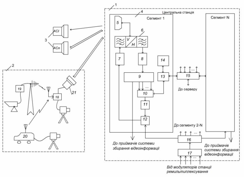 Fig.1
Fig.1
One of duplexer 17 outputs is connected to the downconverter 18 input which is connected by the output to the multiplexer 19 input. The multiplexer 19 is connected by input-output to the user's modem 5 input-output, and by an output is connected to upconverter 20 input which is connected by the output to receive-transmit MW head 2 transmitting part. The user's modem 5 is connected by other input-output to the switchboard 21 input-output which is connected by other input-output to modem 22 input-output which is connected by an output to receive-transmit MW head 2 both amplifiers with gain control 12 and 15 control inputs. One of duplexer 17 outputs is connected to the downconverter 18 input which is connected by the output to multiplexer 19 input. The multiplexer 19 is connected by input-output to the user's modem 5 input-output, and by an output is connected to the upconverter 20 input which is connected by the output to a receive-transmit MW head 2 transmitting part. Other duplexer 17 output is connected to directional coupler 23 input which is connected by the output to the detector 24 input which is connected by the output to encoder/decoder 22 input. Directional coupler 23 by it output is connected to a tuner 4 input from which the signal goes on the subscriber television receiver. The switchboard 21 has the port input of the peripheral user's device with which help it is connected to the user’s computer or a data transmission network.
The first type user's station USn has the switchboard 21, the encoder/decoder 22, the detector 24 and directional coupler 23. In directional coupler 23 broadcasting part of the signal received and converted to a signal of intermediate frequency (IF) in receive-transmit MW head 2, branches off in the passing power detector 24. The signal from the detector 24 arrives in the modem encoder/decoder in which it is digitized. The encoder/decoder 22 forms the data for transfer on a management and monitoring network for their inclusion in the return data link through the user's modem 5, and also will selects and decode the data received from the user's modem 5 under direct data link. On the basis of the management commands received from CS under the direct data link, the management signal intended for gain factor control of both receive-transmit MW head 2 amplifiers with gain control 12 and 15 is formed.
The receive-transmit block of a video information gathering subsystem (Figs. 3) consists of such elements: the receive-transmit MW head 2 antenna 1, the transceiver 3 and the user's modem (CPE) 5. Receive-transmit MW head 2 has no differences from applied in structure USn. The transceiver 3 has following differences (elements of one appointment are numbered equally) concerning the same block USn: it is excluded directional coupler 23, the tuner 4 is excluded, added combiner 25. In use of the tuner 4 as a part of the equipment of video information gathering unattended post there is no necessity. Also there is no necessity in directional coupler 23 as all broadcasting signal goes to the detector 24.
As there is no necessity for the peripheral user’s equipment connection, there is no switchboard 21. The user's modem 5 is used only for management and control signals reception and signaling. After reduction to one kind of all signals arriving on a post, their gathering, multiplexing of the received transport streams in a uniform transport stream and modulations by this stream carrier on intermediate frequency the modulated signal moves on combiner 25. In it this signal unites with a return information channel and goes on receive-transmit MW head 2 transmitting part. Application instead of the video information gathering channel transmitter the receive-transmit block allows to carry out control with CS under the direct data link a video information gathering post receive-transmit block transmit part gain factor and level of its output power that will allow to reduce at signals receiving from several video information gathering posts levels difference on receive CS converters inputs.
In UWMS-R also are applied the second type US (US1) which have no return data link and consequently are not subject to the control and management from CS. By this type US input in their receive converters is applied to a necessary dynamic range maintenance an additional loop of automatic gain control (AGC) which supplements the tuner AGC.
The declared device works as follows. Television broadcast signals are formed by remultiplexing station (on Fig. 1 it is not represented). The remultiplexing station usually represents a teleport which receives signals of satellite, cable, land TV, and also signals from local studio. On CS these signals are properly processed. This processing includes decoding of those signals which are coded by conditional access systems (descrambling), transport streams remultiplexing for the purpose of television programs new packages formation and scrambling these streams by own address coding system. After performance of the specified operations which are necessary for scrambled DVB streams formation, the received data flows are sent on modulators on which outputs are generated carrier, modulated by multi-program TV signals.
The modulated carriers unite in a multi-frequency group signal by means of CS multichannel combiner 17. Further a group signal power shares on N – parts (by quantity of system segments) by means of a power divider 16. On power divider 16 output obtain N - group signal copies, each of which goes on combiner 12 one of CS segments 4. After summation with the direct data link signal this signal will be converted and amplifies by the upconverter 7, then arrives on duplexer 6 input and, having passed it, is radiated by the sector antennas 5 in the form of a beam in width 360 grad./N (where N – quantity of antenna system sectors).
The downstream is formed by a transmitting part of the CS modem 10 (WMTS). In it DVB data packages with time division multiplex (method TDM), modulate preliminary selected carrier, forming the direct data link. Further this signal will be converted by the upconverter to a necessary frequencies range, amplifies and combined with the combiner 12 help with broadcast signals, forming a full group signal of the direct channel. Further it will be converted and amplifies by the upconverter 7 and, having passed through duplexer 6, is radiated by the sector antenna 5 in the form of a beam in width 360 deg. /N (where N – quantity of antenna system sectors). The signal is received by the US of first type USn 3 and video information gathering post receive-transmit blocks.
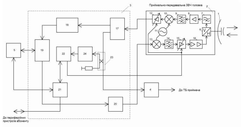
Fig.2
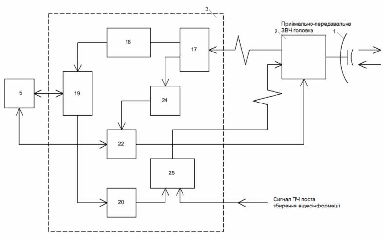
Fig.3
The upstream signals are transferred by USn type station and transmitting parts of video information gathering posts receive-transmit blocks in a corresponding CS sector antenna direction. Frequency and time multiplexing method (method FDMA/TDMA) is thus used. At these multiplexing method use some USn or video information gathering posts receive-transmit blocks quantity works on single frequency and transfers messages in the packages form at the CS modem 10 command. These commands are built in downstream structure in the special channel (control path) form. Such way reaches USn type stations and video information gathering posts receive-transmit blocks collision-less work with which help the information transfer on CS is carried out by them downstream data packages transfer. By the same principle also others USs work which similar USn are working on other frequencies, and also those from them which belong to CS 4 segments with numbers 2 … N.
The video information gathering system has two-level structure. Such construction necessity is caused by that the signals transferred stationary 19 or mobile 20 video information gathering points, can correspond to different standards, for example, DBS – for analogue points and DVB-T – for digital. Besides, for signals of the first level it is heavy to obtain sufficient range by transfer which would allow to transmit directly a signal on CS, because of video information gathering points transmitters (especially mobile) limited power, low placement level of transmitting antennas, and also difficult radio-waves propagation conditions (absence of "line-off-sight” mode, presence of reflected signals considerable quantity etc.). Inclusion in system structure some quantity of video information gathering posts which settle down so that for them the “line-off-sight” mode with CS was provided, allows to solving this problem. Receivers which are a part of video information gathering posts receive-transmit blocks (Figs. 1), accept and process the different signals arriving from video information gathering points, and will convert them to one kind (a kind of standard DVB transport streams TS). Further these TS are multiplexed in the uniform data stream which modulates carrier on intermediate frequency. Then this signal arrives on the transceiver and receive-transmit block 21 receive-transmit MW head in which will be upconverted on frequency and amplify for the further transfer on a radio channel in direction to CS.
On each CS segment 4 signals from USn and video information gathering posts18 which are located in CS antenna sector arrive. Having passed duplexer 6, the received signals arrive on low noise downconverter 8 in which they amplify and will be converted to intermediate frequency signals. Intermediate frequency signals arrive on a multi-channel power divider of the converter 9. This power divider has outputs quantity which is equal to quantity of the CS modem 10 inputs, plus one more output, from which one of received signal copies goes on video information gathering subsystem receivers (on Fig. 1 they are not represented). As these receivers usual DVB tuners can be used.
The network management system (NMS) is concentrated in the central station DOCSIS modem WMTS. It supervises UWMS-R serviceability and parameters by means of the monitoring and management system. Options NMS include the control of network operating modes, administration, and networks attendance and user charge acquisition from users of a network.
The sizes of service zone usually depend on the radio-frequency equipment system gain, also – gain factors of transmit and receive antennas, The region in which system UWMS is placed meteorological characteristics, and also the real signal/noise rate which is reached in system. In general the radius of service zone should be more than 10 Km.
Though spectrum UWMS-R is wide enough in comparison with frequencies bands which are caused for a point-point (PTP) and a point-multipoint (PTM) line types on lower frequencies, in declared system, except frequency and time division, is used as well spatial division of the signals arriving from the USs and video information gathering posts receive-transmit blocks transmitters, for the purpose of increase in their quantity and information capacity of a network.
At increase in CS sectors number the cost because transmitters and receivers should repeat in each of sectors increases also. However sector construction use advantage is that antennas with higher orientation degree which occurs at replacement omnidirectional antennas on sector antennas system, reduces appearance possibility of the effects associated with a multibeam propagation mode, and thereof, reduces an intersymbol interference (ISI). But decided advantage of antenna system sector construction is substantial data transmission network subscriber quantity growth and video information gathering posts quantity growth at the expense of their distribution in space and possibility of a frequencies reuse.
The information UWMS-R part works thus. Transport stream frames contain set distributed in time slots which can be divided on starting slot and arbitrary access slots. To simplify processing process in users modem CPE (decoding), it is necessary, that the passed slots relative quantity in a frame was no more than 7 %. At data transmission rate in a downlink direction 41 Mbit/s, it corresponds to 50 ATM cells or 14 MPEG-2 TS packages in a frame in 6 msec. Everyone CPE then can accept approximately to 3.5 Mbit/s. CS it is capable to transfer some channels simultaneously, however CPE can accept only one channel. It can be switched to different frequencies, but such switching can demand time interval equal to several time slots.
The frames structure is co-ordinate with a transport stream with the image and sound compression standard MPEG-2 (MPEG-2 Transport Stream). MPEG2 – TS MUX package contains 188 byte into which enter one byte of the synchronization, three heading bytes which contain the service information, the information about scrambling and management, and the following 184 MPEG-2 bytes or the additional data. Packages are scrambled with use of pseudo-random binary sequence (PRBS) with the period in 1503 bytes that corresponds to 8 packages. Synchronization bytes are not scrambled. The first synchronization byte is supplemented. According to standard DOCSIS channel coding supposes 5 composed: scrambling, interleaving, block coding Reed – Solomon, convolution coding and, at last, mapping. The downstream uses the norms corresponding to DVB standards for satellite or land services in 11 GHz and 12 GHz ranges. The system is optimized concerning access mode TDM on one carrier, but allows to apply and the scheme of multi-frequency access FDM. As typical rate of data transmission the rate multiple 8 Kbit/s defined. The frame structure is equivalent to specification DAVIC and contains 188 byte.
The access scheme in the upstream is time division multiple access -TDMA. Frame length the same, as for the downstream, that is between 3 msec and 6 msec. CPE regulates the package transfer time moment choice in an uplink direction before coincidence to slot borders in an upstream frame on CS at the set admission on time. Its accuracy is defined by a difference in a propagation delay that is in service zone radius. The network management system distributes set of adjacent time slots so that to generate longer slots the network access, interfering occurrence of collisions by TDMA package transfer which can accompany CPE access to a network. Synchronization is reached thanks to that CPE adapts the slot transfer moment in reply to a feedback by synchronization error until while this error does not become smaller, than one symbol duration in an upstream (the guard interval in a package has the duration equal to 4 symbols). CS generates periodic inquiries about synchronization error for achievement of necessary accuracy. The upstream data package contains 68 byte. The upstream frame contains F slots where number F depends on data transmission rate in an upstream. These F slots are divided on polling slots, arbitrary access slots, and reserve time slots. The each type slots quantity parity is dynamic.
Shortened code Reed - Solomon RS (204,188) is chosen as a block code for an uplink. At input bit error rate (BER) which matters close to 7 х 10 - 4 or less and at unlimited bytes interleaving, the decoder should carry out QEF (quasi error free) output at which BER makes from 10 – 10 to 10 – 11. Convolution interleaver is same most, as well as applied in a downstream under specification DAVIC (T=12, M=17), and also is the block coder. The block decoder should work at input error rate (BER) which is equivalent to "the rigid decision”, which is between 10-4 and 10-2, and should provide BER nearby 2 х 10 – 4 or less.
The roll–off factor for the filter with the type characteristic “a root square of raised cosine” (RSRC) is equal 0.35 that differs from specification DAVIC in which it is applied 0.2 or 0.35 a little. At use of digital filter FIR it is possible to carry out nonlinearity alignment (equalization) in the channel. This filter is not standardizing, therefore it will depend on concrete transfer channel parameters. The modulation scheme is usual Gray-coded QPSK.
The modem of central station DOCSIS – WMTS allows to operate the power given by user's modems, and at the expense of it carries out adaptive suppression of ingress noise in the receiver in real time. Measurement and the analysis of the signal/noise rate in WMTS receiver is for this purpose carried out. On the basis of this analysis special commands for transmitting parts of user's modems control are developed. Further the signal which has arrived in receiver WMTS, is processed in an equalizer that allows to increase throughput of modems DOCSIS at the granting expense practically in all cases of their work possibility in a mode 16QAM instead of QPSK. The equalizer corrects a signal at influence on it frequency fading, amplitude distortions, and also non-uniformity of a group delay. If all the same noise cannot be suppressed (for example, at very big level of ingress noise or a strong interference) WMTS can prevent consequences of noise influence at the expense of modulation type change or transition in a frequency-hopping mode (mode CDMA). For all working as a network part DOCSIS modems parameters improvement, WMTS use the additional receiver which joins in parallel the several receivers intended only for a subscriber’s network service. This receiver gives to operators possibility of an operational administration in any of uplink ports parameters, without forcing thus with their work on servicing. For this purpose the additional receiver joins to in parallel chosen receiver so that the operator could measure the traffic and signal parameters in real time for any of functioning ports. Simultaneously this receiver can have access to the network information and the full list of the user's modems working on any of receivers, subject to monitoring. Thus, while any of receiver ports works at a total load, the additional receiver can increase access to other return channels by tests reception for each of uplink channels and their loading estimation. The auxiliary data transmission network for monitoring and management in active receive-transmit MW heads upconverters and downconverters gain factors can be constructed as usual IP network which uses own wireless data transmission network of UWMS-R as transfer media. On return information UWMS-R channels (upstream) the data intended for levels monitoring of broadcasting signals received the US is transmitted. This data is entered into the return channel by means of the switchboard 21 (Фиг.2). On CS the monitoring data arriving from all active USs, on WMTS 10 output (Fig.1) by means of the switchboard 13 separates from the given clients and goes to the block of monitoring and management 14. Here on the basis of the received data on certain algorithm management commands for each of the US which by means of the switchboard 13 are entered already into the direct data link are developed and transferred on a radio channel simultaneously to all the USs which are in given sector. To reduce quantity of the information intended for the direct channel transfer, the information on receive-transmit MW heads converters gain factors change is transferred only. On each of user's modems (CPE) 5 output all these signals are present and arrive on the switchboard 21 (Fig. 2) with which help the data which concern only control systems separate. In the encoder/decoder 22 the management commands concern to given US are decoded and the given US receive-transmit MW heads up and down converter or the video information gathering posts receive-transmit blocks gain factors control signals will be generated.
Referencies:
- US Patent 2008/0247375A1, pub. 2008.10.09
- Patent of Ukraine № 36562, pub. 27.10.2008, bul. № 20.
The applicant, general director of Company "ROKS" Ksenzenko P. J.
The invention formula
1. UWMS-R that assigns for working in heavy rain regions which includes the central station, a video information gathering subsystem and user's stations, thus the central station has segments, each of which has the sector antenna which on an input-output is connected to a duplexer output-input which on an input is connected to the upconverter, and on an output - with the downconverter which is connected by the output to the downconverters block which N – outputs is connected to the modem (WMTS), and the output connects to video information gathering subsystem receivers, and an output the modem is connected to the upconverter input which is connected by the output to one of combiner inputs which is connected by other input to one of N-channel power divider outputs, and by an output is connected to the upconverter which is connected by an output to a duplexer input, the multichannel power divider by N – outputs is connected with N – segments combiners, and by an input is connected to the multichannel combiner which N – inputs is connected with N – remultiplexing station modulators, differs that the central station modem is connected by an input-output to the switchboard which is connected by one of inputs-outputs to the monitoring and management block, and by other input-output it is connected to a digital platform which by the N – inputs-outputs is connected to N – segments switchboards, and the user's station of the first type has the antenna, receive-transmit MW head, the transceiver, DVB-S tuner and the user's modem (CPE), on a receive-transmit MW head input the polarisation selector which on an input-output is connected to the antenna which is connected by one of inputs to the filter which is connected by the output to a low noise amplifier input which on an output is connected to other filter which on an output is connected to a mixer input, and other mixer input is connected to one of local oscillator outputs, and an output is connected to an input of the first amplifier with gain control is established, the amplifier output is connected to the transceiver, which is connected to a receive-transmit MW head transmitting part mixer input, and other mixer input is connected to other local oscillator output, the mixer output is connected to a filter input which is connected by the output to the second amplifier with the gain control input which input and an input of the first amplifier with gain control are connected to the transceiver, the second amplifier with gain control output is connected to the power amplifier input which is connected by the output to a polarisation selector input, and receive-transmit MW head is connected with the transceiver duplexer, one of duplexer outputs is connected to the downconverter input which is connected by the output to a multiplexer input which is connected by the input-output to an user’s modem input-output, and the output connects to the upconverter input which is connected by the output to a receive-transmit MW head transmitting part, and other duplexer output is connected to a directional coupler input which is connected by the output to the detector, which is connected by an output to the encoder/decoder input which is connected by the input-output to the switchboard, and the switchboard by an input-output is connected to the user's modem, and by other input-exit connected to an external data transmission network, and encoder/decoder by an output is connected to receive-transmit MW head control input, and the directional coupler output is connected to DVB tuner input, and the receive-transmit block consists of the antenna, receive-transmit MW head, the transceiver and the user's modem, receive-transmit MW head which has the structure similar to structure of user’s station receive-transmit MW head, by the receiving part output it is connected to the transceiver duplexer input which is connected by an output to the downconverter which is connected to one of multiplexer inputs which is connected by an output-input to the user’s modem input-output, and by an output it is connected to an combiner input which is connected by an output to a receive-transmit MW head transmitting part, and by other input it is connected to the modulator block output of a video information gathering post, and the transceiver duplexer output is connected to the detector which is connected by an output to the encoder/decoder input which is connected by an output-input to an input-output of the user's modem, and an output the encoder/decoder connected to receive-transmit MW head control input.
2. UWMS-R that assigns for working in heavy rain regions, under item 2 which differs that second type user’s station MW downconverter has auxiliary AGC loop.
The applicant, general director of Company "ROKS" Ksenzenko P. J.
ABSTRACT
Object of invention: UWMS-R that assigns for working in heavy rain regions.
A scope: the useful model concerns radio engineering, in particular to systems which provide television broadcasting, a video information gathering and data transmission within a certain geographical zone on district.
An essence of invention: The central station modem is connected by an input-output to the switchboard which is connected by one of inputs to the monitoring and management block, and by other input-output is connected to a digital platform which by the N – inputs-outputs is connected to N-segments switchboards, and the first type user's station has the antenna, receive-transmit MW head, the transceiver, DVB tuner and the user's modem (CPE), on an input-output of the receive-transmit MW head the polarization selector is placed which on an input-output is connected to the antenna and by one of outputs is connected to the filter which is connected by the output to a low noise amplifier input which on an output is connected to other filter which on an output is connected to a mixer input, and other mixer input the is connected to one of local oscillator outputs, and an output is connected to an input of the first amplifier with gain control, the amplifier output is connected to the transceiver, which is connected to a receive-transmit MW head transmitting part mixer input, and other mixer input is connected to other local oscillator input, the mixer output is connected to a filter input which is connected by the output to an input of the second amplifier with gain control which input and an input of the first amplifier with gain control are connected to the transceiver, the output of the second amplifier with gain control is connected to the power amplifier input which is connected by the output to the polarization selector input, and receive-transmit MW head is connected with transceiver duplexer, one of duplexer outputs is connected to the downconverter input which is connected by the output to the multiplexer input which is connected by the input-output to the user’s modem output-input, and by an output is connected to the upconverter input which is connected by the output to a receive-transmit MW head transmitting part, and other duplexer output is connected to an directional coupler input which is connected by the output to the detector which is connected by an output to encoder/decoder input which is connected by the input-output to the switchboard, and the switchboard by an input-output is connected to the user's modem, and other user’s modem input-output is connected to an external data transmission network, and an output connected to receive-transmit MW head control input, and the directional coupler output is connected to DVB tuner input, and the receive-transmit block consists of the antenna, receive-transmit MW head, the transceiver and the user's modem, receive-transmit MW head having structure which coincides with user’s station receive-transmit MW head structure, by the receiving part output is connected to the transceiver duplexer input which is connected by an output to the downconverter which is connected to one of multiplexer inputs which is connected by an input-output to the user's modem, and by an output it is connected to an combiner input which is connected by an output receive-transmit MW head transmitting part input, and by other input it is connected to the modulator block output of a video information gathering post, and the transceiver duplexer output is connected to the detector, which is connected by an output to a encoder/decoder input, which is connected by an output-input to an user’s modem input-output, and by other output is connected to receive-transmit MW head control input, and the second type user’s station MW downconverter has auxiliary AGC loop.
Technical result: provides essential increase in a dynamic range at USs receivers inputs, levels difference reduction of the signals radiated by transmitters of video information gathering posts receive-transmit blocks transmitters and, thus, CS segments receivers necessary dynamic range reduction. The device survive during heavy rains, but it can be used and in usual conditions as the given device allows to lower expenses for installation of system and to lower operational expenses.